TI MSPM0 智能车控制系统TI MSPM0 · Embedded Vehicle Control
基于 MSPM0G3507,连接 11 路灰度、惯性输入和电机驱动,用 C、Timer/PWM 与 PID 实现采样到执行流程,开展电机调试和参数整定。An MSPM0G3507 vehicle project connecting 11-channel grayscale sensing, inertial input and motor drive through embedded C, timer/PWM control and PID tuning.
- 01输入Input11 路灰度 + IMU11-Channel Grayscale + IMU
- 循迹输入 · ICM20608Line sensing · ICM20608
- 02控制ControlMSPM0G3507MSPM0G3507
- C · 定时调度 · PIDC · Timed scheduling · PID
- 03执行ActuationPWM / 电机驱动PWM / Motor Driver
- Timer/PWM · AT8236Timer/PWM · AT8236
项目背景Project Overview
以 MCU 为中心组织循迹传感、惯性输入和电机执行,应用程序负责采样、控制计算及输出。控制程序资料保留驱动接口与参数;独立的 2024“双层”板级工程作为设计归档另列。The MCU coordinates line sensing, inertial input and motor actuation, with application firmware handling acquisition, control computation and output. Firmware records retain driver interfaces and parameters; the separate 2024 “双层” board project is presented as a design archive.
技术目标Engineering Objective
在 MCU 资源和控制周期约束下,将灰度与惯性信息接入控制程序,通过参数整定建立可调试的电机响应,并明确区分应用逻辑、外设驱动与硬件接口。Integrate grayscale and inertial input within MCU resource and timing constraints, tune motor response, and keep application logic, peripheral drivers and hardware interfaces clearly separated.
系统架构System Architecture
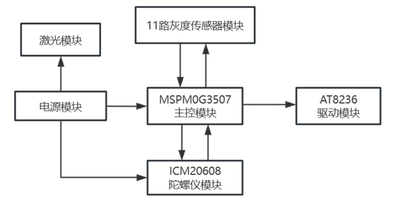
- 01输入:11 路灰度、ICM20608 及反馈接口。Input: 11 grayscale channels, ICM20608 and feedback interfaces.
- 02处理:MSPM0G3507 上的 C 应用逻辑与定时调度。Processing: embedded C application logic and timed scheduling on MSPM0G3507.
- 03控制:目标值/反馈值计算、PID 参数与输出限幅。Control: setpoint/feedback computation, PID parameters and output limiting.
- 04执行:Timer/PWM 输出经 AT8236 电机驱动到执行机构。Actuation: timer/PWM outputs through AT8236 motor drivers.
关键技术实现Technical Implementation
传感器与控制接口Sensor and control interfaces
将灰度、惯性输入与电机控制分成采样、控制计算和输出三个环节。项目接口包含传感器、显示与电机驱动,便于逐段检查输入是否正确进入控制器。Separate acquisition, control computation and output. Sensor, display and motor-driver interfaces allow the input-to-controller path to be inspected one stage at a time.
C 语言 PID 与电机控制Embedded C PID and motor control
归档应用代码包含目标/反馈误差、积分限幅、输出限幅和积分分离选项;电机控制程序保留位置式与增量式速度控制路径。参数整定结合电机方向、反馈和响应进行。The archived application code includes setpoint/feedback error, integral and output limits, and optional integral separation. Motor-control code retains positional and incremental speed-control paths. Tuning checks motor direction, feedback and response.
独立控制板设计归档Separate controller-board design archive
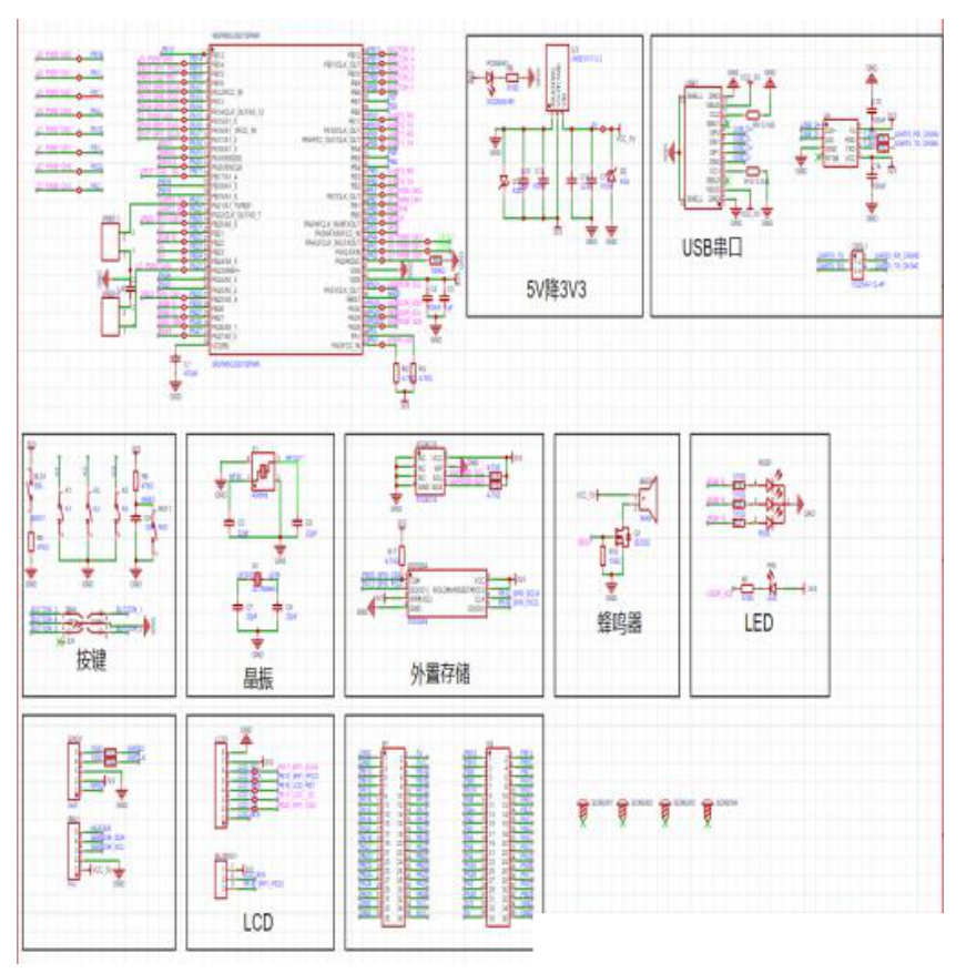
独立的 2024“双层”嘉立创EDA工程采用 MSPM0G3507SPMR,图纸包含 3.3V 电源、USB/UART、外部存储和调试接口。该设计归档与比赛控制程序、历史 MSPM0 PCB PDF 分别展示,不代表三者已映射到同一最终参赛板。The separate 2024 EasyEDA project named “双层” uses MSPM0G3507SPMR, with 3.3V power, USB/UART, external storage and debug interfaces. This archive, the competition firmware and historical MSPM0 PCB PDFs are presented as distinct records, without assigning all three to one final competition board.
系统与板卡版本System and board revisions
ZJA460《自动行驶小车》描述 LP-MSPM0G3507 主控、11 路灰度、ICM20608、AT8236 和编码器/显示接口。报告第2页说明:选用12路灰度模块,再结合单个传感器组成实际11路阵列。报告中的两轮差速车与后续四轮 mini 舵机车分别记录。The ZJA460 vehicle report describes LP-MSPM0G3507, an 11-channel grayscale array, ICM20608, AT8236 and encoder/display interfaces. Page 2 explains the use of a 12-channel module and individual sensors to form an 11-channel array. The differential-drive vehicle and later four-wheel mini servo vehicle are separate configurations.
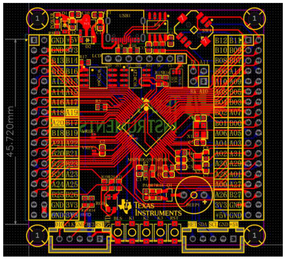
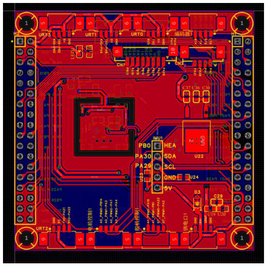
V1 与“双层”使用相同原理图,但 PCB 层设置不同:V1 启用 Top、Bottom、GND 和 VCC;“双层”仅启用 Top/Bottom。两版均包含 MSPM0G3507SPMR、AMS1117-3.3、CH340N、AT24C16 与 W25Q64,适合比较 MCU 扇出、供电和存储接口布置。V1 and “双层” share the same schematic but use different PCB layer definitions: V1 enables Top, Bottom, GND and VCC; “双层” enables Top/Bottom only. Both include MSPM0G3507SPMR, AMS1117-3.3, CH340N, AT24C16 and W25Q64, supporting comparison of MCU fan-out, power and storage interfaces.
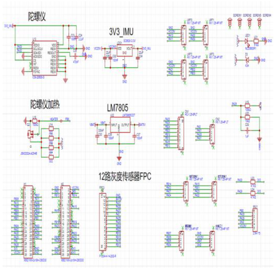
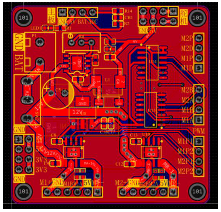
7.18 纠错版是另一组拓展板资料:源工程包含 ICM-20608-G、SC662K-3.3V、LM78M05CDT 和连接器,没有与 V1 相同的 MSPM0 芯片实例。应按主控板、拓展板和驱动模块的系统关系阅读,不能仅凭文件名排成同一块板的迭代链。The July 18 corrected archive is a different expansion-board design containing ICM-20608-G, SC662K-3.3V, LM78M05CDT and connectors, without the same MSPM0 device instance as V1. Read it as part of a controller/expansion/driver system rather than assuming one linear board revision history.
固件调度与传感输入Firmware scheduling and sensor input
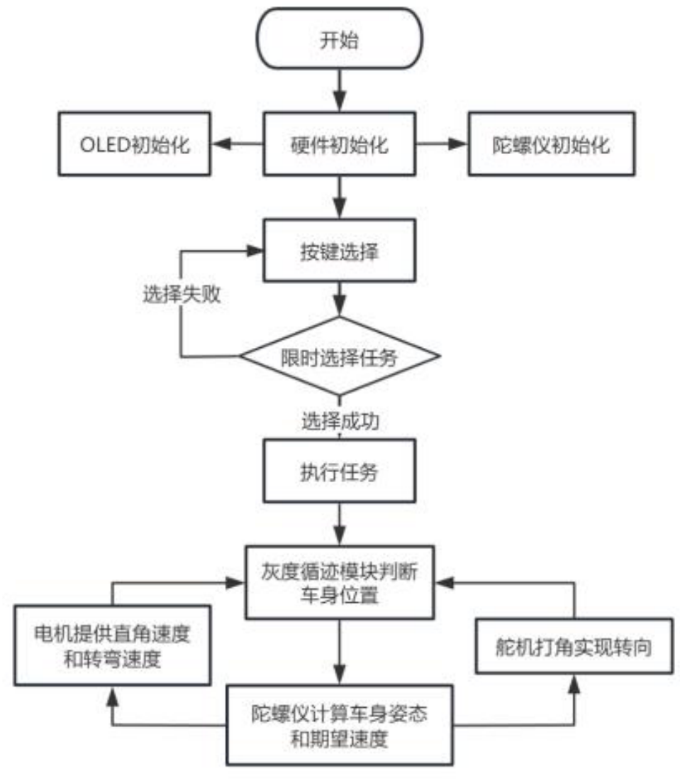
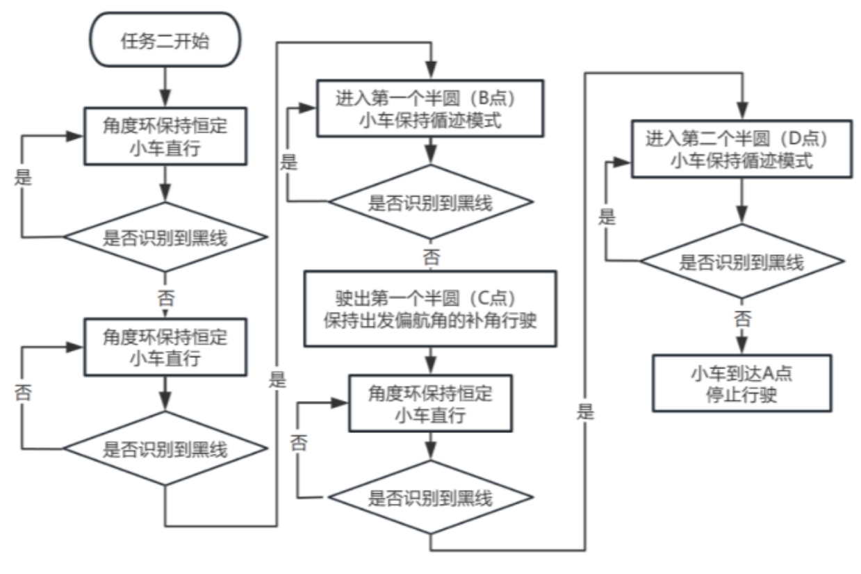
June 28 归档分为 user、apply 和 driver。main() 初始化外设后在前台执行 screen_display() 与 adc_statemachine();driver/ntimer.c 将 TIMER_1 中断接到 maple_duty_200hz(),配置为5ms;TIMER_G12 接到 duty_1000hz(),配置为1ms。这些是源码配置周期,不是实测时序。The June 28 archive separates user, apply and driver layers. After initialization, main() runs screen_display() and adc_statemachine() in the foreground. driver/ntimer.c connects TIMER_1 to maple_duty_200hz() with a configured 5 ms period and TIMER_G12 to duty_1000hz() with a configured 1 ms period. These are configuration values, not measured timing.
灰度输入使用 GPIO 数字位,不是12通道模拟 ADC。gpio_input_check_channel_12() 读取12个输入,用位模式查表得到横向偏差;异常模式保留历史值并增加异常计数。两个12路函数的打包循环均为 i<11,第12个读取位没有进入状态字;这需要结合实际接线检查,不能直接证明它就是参赛11路配置的有意实现。Grayscale sensing uses digital GPIO bits rather than a 12-channel analog ADC. gpio_input_check_channel_12() reads twelve inputs and maps bit patterns to lateral error; unrecognized patterns retain history and increment an error counter. Both twelve-channel routines pack with i<11, omitting the twelfth read bit. This needs wiring-level review and does not establish an intentional mapping to the competition’s eleven-channel array.
imu_data_sampling() 调用 ICM206xx_Read_Data(),对陀螺仪和加速度分别配置 Butterworth 低通;trackless_ahrs_update() 使用无磁力计姿态更新。vision.c 则是带帧头与校验的视觉串口解析模块;模块存在不代表 ZJA460 H题车辆使用相机,报告明确采用灰度感知。imu_data_sampling() calls ICM206xx_Read_Data() and applies separately configured Butterworth filters to gyro and acceleration data. trackless_ahrs_update() uses a magnetometer-free attitude update. vision.c contains framed, checksum-based visual UART parsing; its presence does not mean that the ZJA460 H-task vehicle used a camera, since the report specifies grayscale sensing.
电机闭环与调试要点Motor feedback and debugging
speed_control_100hz() 的普通双轮分支每两次调用更新一次。默认位置式分支由比例项和积分项组成,另有增量式 PI 路径;误差、积分和输出分别限幅。不能仅凭 PID 命名就宣称每个速度分支都使用了微分项。The normal two-wheel branch in speed_control_100hz() updates once every two calls. The default positional branch combines proportional and integral terms, with an alternative incremental PI path; error, integral and output are independently limited. A PID-related name does not establish derivative action in every speed-control branch.
motor_output() 根据模式选择左右输出,锁定时强制归零,再限制到 ±999,通过 TIMA0 四个比较通道控制方向和占空比。接口映射为右侧 PA4/PA7、左侧 PA3/PB14。联调先核对电机方向、编码器符号与零输出保护,再比较目标速度、反馈速度和饱和持续时间。motor_output() selects left/right commands by mode, forces zero when locked, clamps to ±999 and drives four TIMA0 compare channels for direction and duty. The mapped pins are PA4/PA7 on the right and PA3/PB14 on the left. Debugging should establish motor direction, encoder sign and zero-output behavior before comparing setpoint, feedback and sustained saturation.
June 28 固件基于保留“无名创新”署名的框架。个人工作集中在应用、传感接口与系统联调;本节分析控制逻辑与调试要点,具体参赛烧录版本单独记录。The June 28 firmware builds on a framework credited to “无名创新”. My work focuses on application, sensor interfaces and system integration. This section explains control logic and debugging considerations; competition firmware revisions are tracked separately.
团队报告中的测试与设计取舍Team-reported tests and design tradeoffs
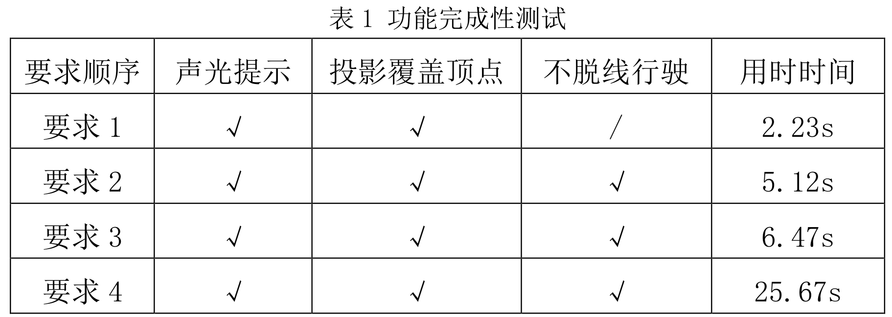
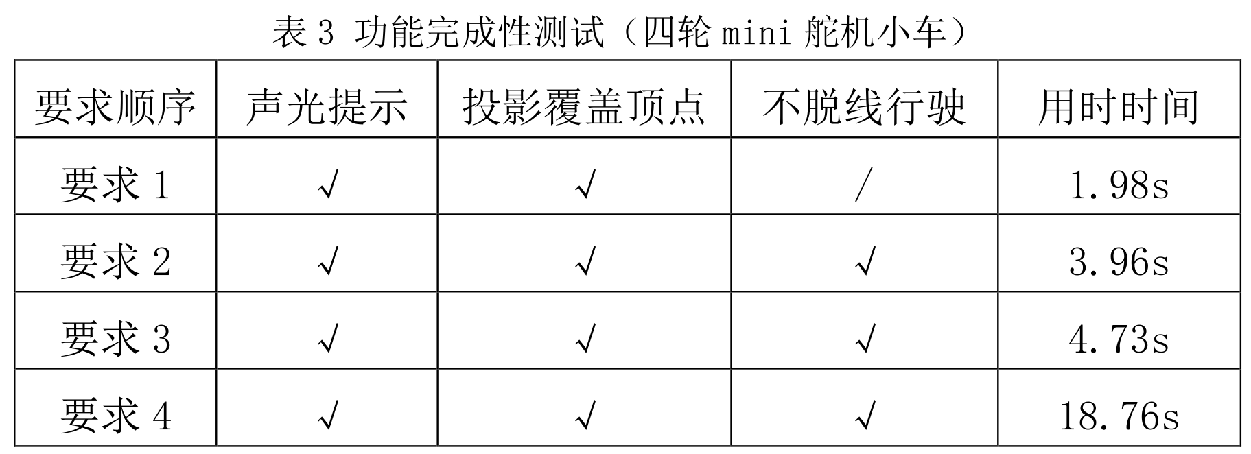
ZJA460 第8页表1记录两轮差速车各要求连续三次测试的平均用时:2.23、5.12、6.47、25.67秒;第9页表3记录四轮 mini 舵机车对应平均值:1.98、3.96、4.73、18.76秒。两组数据对应不同车模,作为团队报告结果呈现,不视为本轮复测或同条件独立基准。ZJA460 PDF page 8, Table 1 reports three-trial average times for the differential-drive vehicle: 2.23, 5.12, 6.47 and 25.67 seconds. Page 9, Table 3 reports 1.98, 3.96, 4.73 and 18.76 seconds for the four-wheel mini servo vehicle. These refer to different configurations and are team-reported results, not new measurements or a controlled independent benchmark.
报告解释了差速转弯减速与舵机转向之间的取舍,同时说明 mini 车只有一天调试时间,转向稳定性和精度仍需提高,测试时可能优先采用两轮车。2024 TI 杯本科组二等奖对应 ZJA460 团队作品;该关联不指定任何独立归档 PCB 为最终获奖板。The report discusses the tradeoff between slowing wheels for differential steering and using servo steering. It also states that the mini vehicle had only one day of tuning, with remaining steering stability and accuracy issues, so the two-wheel vehicle might be preferred in testing. The 2024 TI Cup undergraduate second prize is associated with the ZJA460 team entry; this does not identify an archived PCB as the final award-winning board.
获奖证书编号:ZJJS2024240184Award certificate no.: ZJJS2024240184
来源:ZJA460 PDF第8–9页表1、表3与总结;用户确认奖项对应。Sources: ZJA460 PDF pp. 8–9, Tables 1 and 3 and conclusion; user-confirmed award attribution.我的实际工作My Contributions
- 参与 MSPM0 应用程序、传感器接口和控制系统调试。Contributed to MSPM0 application firmware, sensor interfaces and control-system debugging.
- 使用 C、Timer/PWM 和 PID 组织电机控制流程及参数整定。Used C, timer/PWM and PID to organize motor control and parameter tuning.
- 结合驱动程序、硬件接口和电机响应进行系统联调。Integrated driver code, hardware interfaces and motor response.
项目成果与验证Results & Validation
技术栈Tech Stack
工程技术深入Technical Deep Dive
以控制器状态、限幅和 IMU 寄存器读回为切入点阅读 MSPM0 代码,同时把第三方控制框架、个人应用调试与独立 PCB 归档分开。Read MSPM0 code through controller state, limits and IMU register readback, keeping third-party framework routines, personal application integration and the separate PCB archive distinct.
工程问题与模块职责Engineering question and responsibilities
如何让传感输入、PID 状态与电机方向保持一致,并把参数配置和实际验证区分开?How can sensor input, PID state and motor direction remain consistent while separating configuration from measured validation?
小车控制主线为 MSPM0G3507、灰度/惯性输入和 AT8236 电机执行。下文所读 ncontroller 归档含厂商框架,不将全部驱动与控制例程写成本人原创。The vehicle-control context uses MSPM0G3507, grayscale/inertial input and AT8236 actuation. The reviewed ncontroller archive includes vendor framework code; its drivers and control routines are not all attributed to me.
PID 状态与输出约束PID state and output constraints
所读控制器例程Reviewed controller routine
- 01目标 − 反馈Setpoint − feedback
- 02误差历史 / 差分Error history / difference
- 03积分分离与积分限幅Integral separation / clamp
- 04P + I + DP + I + D
- 05输出限幅 / 执行接口Output limit / actuation
01传感接口与三套资料边界Sensor interfaces and three separate records
项目资料Project Records
项目传感与执行主线包含 11 路灰度、ICM20608 和 AT8236。独立 2024“双层”板的原生图纸则标有 MSPM0G3507SPMR、AMS1117-3.3、CH340N、AT24C16、W25Q64 及调试/扩展接口;不能反向把这些全部当作竞赛车已装配器件。The vehicle project context includes eleven grayscale channels, ICM20608 and AT8236. The separate 2024 “双层” drawing labels MSPM0G3507SPMR, AMS1117-3.3, CH340N, AT24C16, W25Q64 and debug/expansion interfaces; these are not all assigned to the competition vehicle as fitted parts.
比赛控制程序、历史 MSPM0 PCB/原理图 PDF 和新“双层”设计分别管理。已有 Top/Bottom 两铜层软件设置确认,但制造、焊接、上电和最终装车需要对应修订的记录。Competition firmware, historical MSPM0 PCB/schematic PDFs and the separate “双层” design remain distinct. Top/Bottom copper is confirmed in the EDA configuration; fabrication, assembly, power-on and final vehicle use require revision-specific records.
来源:既有系统资料与独立 2024 原生原理图Source: existing system material and the separate 2024 native schematic
02调度与 IMU 初始化检查Scheduling and IMU initialization checks
归档代码Archived Code
归档定时器 IRQ 分别调用不同 duty 回调,PWM 比较寄存器写入由驱动接口封装。回调名中的频率不直接当作最终实测周期;应同时核对定时器配置和执行路径。Archived timer IRQs invoke different duty callbacks, and driver interfaces wrap PWM compare-register writes. Frequency-like callback names are not taken as final measured periods; timer configuration and execution paths must agree.
ICM206xx 初始化先复位并读取 WHO_AM_I,按识别结果配置传感器,再读回寄存器与期望值比较;数据读取路径将连续字节组成有符号轴值。该驱动支持多个器件分支,不能把另一型号分支的量程直接套给 ICM20608。ICM206xx initialization resets the device, reads WHO_AM_I, selects a device branch, configures registers and compares readback against expected values. The read path combines bytes into signed axes. Because the driver supports multiple devices, ranges from another branch are not assigned to ICM20608.
来源:归档定时器与多型号 IMU 驱动Source: archived timer and multi-device IMU driver
03PID 数据结构与限幅路径PID state and limiting paths
归档代码Archived Code
控制器保存 expect、feedback、error、历史误差、integral 和 output。运行时先更新误差历史,用目标减反馈形成新误差,差分可跨配置的历史间隔;之后执行可选误差限幅、积分分离、积分限幅和总输出限幅。The controller retains expect, feedback, error, error history, integral and output. It updates history, forms setpoint-minus-feedback error and differences against a configured history gap, then applies optional error limiting, integral separation, integral clamping and output clamping.
电机控制框架保留位置式与增量式速度控制分支,并分别处理左右反馈及输出。带 dt 的 PID 例程检查时间间隔,在异常区间回退到传入 dt;这些是所读实现机制,不是新的调参成绩。The motor framework retains positional and incremental speed-control branches with separate wheel feedback/output. A dt-aware PID routine checks the interval and falls back to the supplied dt outside its accepted range. These are implementation mechanisms, not new tuning results.
ctrl->last_error=ctrl->error;
ctrl->error=ctrl->expect-ctrl->feedback;
ctrl->dis_error=ctrl->error-ctrl->error_backup[ctrl->dis_error_gap_cnt-1];
来源:归档 PID 与电机控制框架Source: archived PID and motor-control framework
04积分、时间基准与输出饱和Integral state, timing and saturation
工程分析Engineering Analysis
积分限幅防止积分状态无限增长,输出限幅约束最终执行值;二者作用层次不同。分析还要检查切换模式或停车时是否清除积分,以及误差历史间隔是否处于数组有效范围。Integral clamping limits accumulated state, whereas output clamping constrains the final actuator request. They act at different levels. Review also checks integral reset at stops/mode changes and valid bounds for the history-gap index.
位置式与增量式控制的输出递推不同,参数不宜跨模式直接复用。编码器符号、电机方向、PWM 范围和时间基准应先一致,再比较控制响应。Positional and incremental controllers update output differently, so parameters should not be transferred blindly. Encoder sign, motor direction, PWM range and timing should agree before comparing response.
工程分析:基于当前控制器和电机分支Engineering analysis: based on the reviewed controller and motor branches
05从寄存器到电机响应的检查点Checkpoints from registers to motor response
工程分析Engineering Analysis
可按设备 ID、配置读回、原始轴值、轴方向与零偏、目标/反馈误差、限幅前后输出、PWM 方向分段观察。把传感故障和电机方向错误与 PID 增益问题分开,避免用参数掩盖接口问题。Useful observations progress through device ID, configuration readback, raw axes, orientation/bias, target/feedback error, output before/after limiting and PWM direction. Sensor and direction faults should be separated from PID-gain issues.
工程分析:由现有读回与控制状态确定检查点Engineering analysis: checkpoints from readback and controller state
06控制应用与设计归档的验证范围Validation scope of application and archive
项目资料Project Records
既有成果为 2024 TI 杯浙江省大学生电子设计竞赛本科组二等奖及控制程序归档。本人范围仍是应用程序、传感接口、电机调试与系统联调,不扩大为所有 SDK、例程或独立控制板的原创设计。The established outcome is undergraduate second prize in the 2024 Zhejiang TI Cup and an archived control application. My scope remains application firmware, sensor interfaces, motor debugging and integration, without claiming authorship of every SDK routine or the separate board.
本页结合固件实现与 ZJA460 团队报告讲解控制系统。测试数据采用报告中的车模配置与测试条件;独立板卡设计与参赛硬件分别说明。This page connects firmware implementation with the ZJA460 team report. Test data retains the report’s vehicle configurations and conditions; separate board designs are distinguished from competition hardware.
来源:项目分工、固件实现与设计报告Source: project responsibilities, firmware implementation and design report
面试深入讨论Interview Deep Dive
从设计问题与已有实现出发,进一步讨论边界、观察量和验证方法。Follow the design questions and implementation details into scope, observables and validation methods.
积分限幅和输出限幅是否重复?Are integral and output limits redundant?
不是:一个约束内部累计状态,一个约束执行请求;应结合模式切换和饱和后的恢复分析。No. One constrains accumulated internal state and the other the actuator request; recovery and mode changes should be analyzed separately.
多型号 IMU 驱动为何先读 WHO_AM_I?Why read WHO_AM_I in a multi-device IMU driver?
同一驱动包含不同初始化和轴数据分支,设备身份决定配置路径;文件名不能独自证明当前运行型号。The driver contains device-specific initialization and axis branches. Identity selects the path; the filename alone does not establish the running sensor.
这段代码能否证明最终控制频率?Does this code establish final control frequency?
需要定时器配置、回调路径和运行测量一起支持;回调名或注释只提供线索。Timer configuration, callback paths and runtime measurements must support it together; names and comments are clues only.
工程备注 · 阶段与版本Engineering Notes · stage & revisions
- 比赛控制系统、“双层”EDA设计及旧 MSPM0 PCB PDF 分属不同版本资料;旧图纸使用的核心板和电机接口不直接套用于新设计。The competition control system, the “双层” EDA design and older MSPM0 PCB PDFs are separate revision records; old core-board and motor-interface details are not assigned to the newer design.
- “双层”的完成阶段为原理图/PCB设计;其个人设计范围、制造、焊接、上电及最终装车情况按对应版本确认。SDK 和示例驱动与本人应用代码分别看待。The “双层” record represents schematic/PCB design. Personal design scope, fabrication, assembly, power-on and final vehicle use require revision-specific confirmation. SDK/example drivers are distinct from personal application work.
- June28 固件保留第三方框架作者标记;ZJA456 是独立激光追踪报告,用户确认其为成功参赛奖,不属于本项目二等奖。The June28 firmware retains third-party framework author headers. ZJA456 is a separate laser-tracking report, identified by the user as a successful-participation award rather than this project’s second prize.
硬件架构与 PCB 设计Hardware Architecture & PCB Design
从电源、传感接口和控制器到板级布局,补充介绍项目的硬件设计资料。Power, sensor interfaces, controller design and board layout provide a closer look at the project hardware.
独立 MSPM0 控制板设计归档Separate MSPM0 Controller-Board Design Archive
Design Archive · 原理图与 PCBDesign Archive · schematic & PCB
嘉立创EDA“双层”控制板设计,以 MSPM0G3507SPMR 为核心,整合 3.3V 电源、USB 串口、外部存储与扩展接口。The EasyEDA “双层” controller design combines MSPM0G3507SPMR with 3.3V power, USB serial, external storage and expansion interfaces.
设计背景与板卡定位Design Objective
为 MSPM0 控制器组织供电、存储、通信与调试接口。Organize power, storage, communication and debug interfaces around the MSPM0 controller.
电路架构与主要器件Circuit Architecture
- MSPM0G3507SPMR;AMS1117-3.3 的 5V→3.3V 电源网络。MSPM0G3507SPMR with an AMS1117-3.3 5V-to-3.3V supply network.
- 原理图标注 USB-C / CH340N、AT24C16 与 W25Q64,另有 SWD 与 IMU 扩展接口。The schematic labels USB-C/CH340N, AT24C16 and W25Q64, with SWD and IMU expansion headers.
- EDA 设置启用 Top/Bottom 两铜层;Layout 可从 MCU 扇出、电源和接口分区讲解。The EDA configuration enables Top/Bottom copper; layout discussion covers MCU fan-out, power and interface placement.
Layout 与电路讲解Layout & Circuit Walkthrough
- 归档包含 MSPM0G3507 控制板的原理图、PCB 及封装依赖。EDA 工程已确认启用顶层和底层两个铜层,可用于分析主控布局、供电网络及接口设计。The archive contains the MSPM0G3507 schematic, PCB layout, and footprint dependencies. The EDA design has Top and Bottom copper layers enabled, supporting a review of controller placement, power networks, and interfaces.
- 可定位讲解电源输入、USB/UART、外部存储和调试接口的连接关系。The material supports discussion of power input, USB/UART, storage and debug connections.
工程备注 · 完成阶段与分工Engineering Notes · stage & contribution
完成阶段为原理图/PCB设计归档;制造、焊接、上电和装车状态按对应版本确认。Stage: schematic/PCB design archive. Fabrication, assembly, power-on and vehicle use require revision-specific confirmation.
本节展示控制板设计资料;个人贡献以项目页所述控制应用、接口与系统联调为范围。This section presents controller-board design material. Personal contributions are scoped to the control application, interfaces and integration described on the project page.
- 比赛控制程序、2024“双层”嘉立创EDA工程与历史 MSPM0 PCB PDF 分别记录,尚未将三者对应到同一最终参赛板;图纸接口不证明器件已装配。The competition firmware, the 2024 EasyEDA “双层” project and historical MSPM0 PCB PDFs are separate records, without a confirmed mapping to one final competition board. Interface labels do not establish fitted devices.