DESIGN ARCHIVE / 01
EDA · MSPM0G3507
独立 MSPM0 控制板设计归档Separate MSPM0 Controller-Board Design Archive
嘉立创EDA“双层”控制板设计,以 MSPM0G3507SPMR 为核心,整合 3.3V 电源、USB 串口、外部存储与扩展接口。The EasyEDA “双层” controller design combines MSPM0G3507SPMR with 3.3V power, USB serial, external storage and expansion interfaces.
Design Archive · 原理图与 PCBDesign Archive · schematic & PCB
电路与设计说明Circuit & design details
- MSPM0G3507SPMR;AMS1117-3.3 的 5V→3.3V 电源网络。MSPM0G3507SPMR with an AMS1117-3.3 5V-to-3.3V supply network.
- 原理图标注 USB-C / CH340N、AT24C16 与 W25Q64,另有 SWD 与 IMU 扩展接口。The schematic labels USB-C/CH340N, AT24C16 and W25Q64, with SWD and IMU expansion headers.
- EDA 设置启用 Top/Bottom 两铜层;Layout 可从 MCU 扇出、电源和接口分区讲解。The EDA configuration enables Top/Bottom copper; layout discussion covers MCU fan-out, power and interface placement.
归档包含 MSPM0G3507 控制板的原理图、PCB 及封装依赖。EDA 工程已确认启用顶层和底层两个铜层,可用于分析主控布局、供电网络及接口设计。The archive contains the MSPM0G3507 schematic, PCB layout, and footprint dependencies. The EDA design has Top and Bottom copper layers enabled, supporting a review of controller placement, power networks, and interfaces.
工程备注 · 阶段与分工Engineering Notes · stage & contribution
完成阶段为原理图/PCB设计归档;制造、焊接、上电和装车状态按对应版本确认。Stage: schematic/PCB design archive. Fabrication, assembly, power-on and vehicle use require revision-specific confirmation.
本节展示控制板设计资料;个人贡献以项目页所述控制应用、接口与系统联调为范围。This section presents controller-board design material. Personal contributions are scoped to the control application, interfaces and integration described on the project page.
- 比赛控制程序、2024“双层”嘉立创EDA工程与历史 MSPM0 PCB PDF 分别记录,尚未将三者对应到同一最终参赛板;图纸接口不证明器件已装配。The competition firmware, the 2024 EasyEDA “双层” project and historical MSPM0 PCB PDFs are separate records, without a confirmed mapping to one final competition board. Interface labels do not establish fitted devices.
阅读技术说明Read Technical Notes
按 MCU、5V→3.3V、USB/UART、外部存储及 SWD 阅读原生图纸;独立 2024 工程与竞赛控制程序、历史 PDF 分开。Read the native drawing through MCU, 5V-to-3.3V power, USB/UART, external storage and SWD. The separate 2024 project remains distinct from competition firmware and older PDFs.
Top/Bottom 是软件铜层设置与原生导出的视图范围,不能直接当作制板、装配或实车运行证明。Top/Bottom describes configured copper and native-view scope, not fabrication, assembly or vehicle-operation proof.
进入项目技术章节Open the technical chapter →DESIGN ARCHIVE / 02
EDA · Altium Designer
wushua 无刷驱动电路归档(Altium)wushua · Brushless Driver Circuit Archive
Altium 原理图标注 STC32G12K128、FD6288Q、SE8650KX-LF 和六个 TPN2R703NL MOSFET,包含电源、换向检测及信号输入模块。The Altium schematic labels STC32G12K128, FD6288Q, SE8650KX-LF and six TPN2R703NL MOSFETs, with supply, commutation-detection and signal-input sections.
Design Archive · 多版本 LayoutDesign Archive · layout revisions
电路与设计说明Circuit & design details
- 主控 U4:STC32G12K128-48PIN;预驱 U1:FD6288Q。Controller U4: STC32G12K128-48PIN; predriver U1: FD6288Q.
- 稳压标注 U2:SE8650KX-LF;功率开关 Q1–Q6:TPN2R703NL。Regulator label U2: SE8650KX-LF; switches Q1–Q6: TPN2R703NL.
- 图纸包含电池电压检测、换向检测电阻/RC网络、MOS 预驱和三相端子。The schematic contains battery-voltage sensing, commutation-detection resistor/RC networks, MOS predrive and three-phase terminals.
从控制信号、预驱到 MOSFET 模块阅读原理图,结合大焊盘、控制器扇出和功率铜连接比较 Layout。Read the schematic from control input through predrive to MOSFETs, and compare layout at the large pads, MCU fan-out and power copper.
工程备注 · 阶段与分工Engineering Notes · stage & contribution
展示阶段为电路与 Layout 设计归档;额定电压/电流、制造及电气测试尚需对应版本记录。Stage: circuit/layout design archive. Voltage/current ratings, fabrication and electrical tests require revision-specific records.
本节为电机驱动设计资料展示,不将整套原理图、Layout 或固件归为个人独立成果。This is a motor-driver design collection; the complete schematic, layout and firmware are not attributed to me as independent work.
- 器件名称为原理图标注;最终版本选择及实物采用情况按工程记录确认。Device names are schematic labels. Final revision selection and physical use depend on project records.
阅读技术说明Read Technical Notes
原理图标注 U4 STC32G12K128、U1 FD6288Q、U2 SE8650KX-LF、Q1–Q6 TPN2R703NL,可沿控制、预驱与功率器件逐层阅读。The schematic labels U4 STC32G12K128, U1 FD6288Q, U2 SE8650KX-LF and Q1–Q6 TPN2R703NL, supporting a reading from control through predrive to power devices.
三个 PCB 修订分别比较接口扇出、功率连接与布局;不据器件名称推定额定功率、最终版、保护性能,或与 ADV/STC32 参赛板绑定。Compare interface fan-out, power connections and placement across three PCB revisions, without inferring ratings, final revision, protection performance or a link to ADV/STC32 competition boards.
DESIGN ARCHIVE / 03
EDA · STC32 / Team Project
STC32 多板卡工程STC32 multi-board system
控制板、12 路放大板和供电模块构成板级设计资料。模拟前端采用重复通道布局,系统工作连接 OPA4377、ADC 与 MCU 控制。The design material includes a controller, a 12-channel amplifier and power modules. Repeated analog-channel layouts connect OPA4377 conditioning, ADC acquisition and MCU control.
Competition Hardware · 设计资料Competition Hardware · design material
电路与设计说明Circuit & design details
- 放大板图纸标注三颗 OPA4377 与 RP1–RP12 调节网络。The amplifier schematic material labels three OPA4377 devices and RP1–RP12 adjustment networks.
- 控制板可定位核心板插座、UART/HS_SPI、按键与电源区域。The controller layout identifies core-board headers, UART/HS_SPI, buttons and power sections.
- 供电、模拟和控制接口分别检查,结合 ADC 读数与 PWM 响应联调。Power, analog and control interfaces are checked separately alongside ADC readings and PWM response.
设计资料支持讨论模拟通道重复布局、接口扇出、供电分区与底层铺铜。The design material supports discussion of repeated analog channels, interface fan-out, power placement and bottom-layer copper.
工程备注 · 阶段与分工Engineering Notes · stage & contribution
系统竞赛经历与板卡设计归档分层展示;各修订的制造、测试和装车对应按板卡记录。The competition system and board-design archive are presented separately; fabrication, tests and vehicle mapping are revision-specific.
项目工作包括硬件与嵌入式开发及系统联调;每块归档 PCB 的具体设计范围另按板卡说明。Project work includes hardware, embedded development and system integration; responsibility for each archived PCB is described separately.
- 12 路双 STC32F 与旧 10 路 STC32G 资料分别归档;逐板设计贡献及最终装车修订需具体确认。The 12-channel dual-STC32F and older 10-channel STC32G material are separate; personal board-design scope and final vehicle revisions require specific confirmation.
阅读技术说明Read Technical Notes
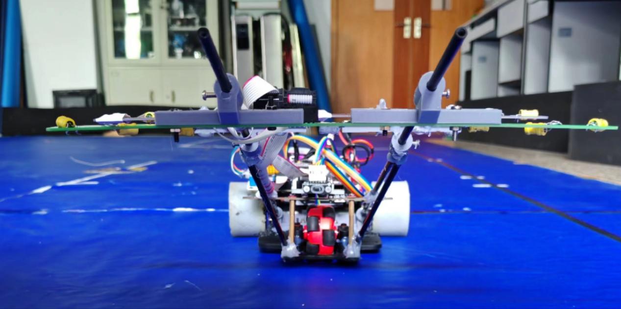
检查表五板为两块电磁杆、运放板、驱动板和主板;额外电源模块作为独立归档,不并入这份五板申报清单。The declared five boards are two inductor rods, an amplifier, driver and mainboard. Extra power modules are separate archives, not additions to this declaration.
三颗 OPA4377 与 RP1–RP12 支持模拟通道阅读;12 路硬件与已读十通道代码需要版本映射后才能给出最终 ADC 接线。Three OPA4377s and RP1–RP12 support analog-channel review; twelve-sensor hardware and reviewed ten-channel code require revision mapping before final ADC wiring is assigned.
进入项目技术章节Open the technical chapter →DESIGN ARCHIVE / 04
CAD · SolidWorks / Design Concept
魔镜 SolidWorks 机械设计Smart Mirror · SolidWorks CAD
SolidWorks 装配、零件及工程图资料,用于讲解机械结构、零件接口与总装关系,并与机器人方案材料配合阅读。SolidWorks assembly, part and drawing material for discussing structure, part interfaces and assembly relationships alongside the robot concept.
Design Archive · CAD / DrawingsDesign Archive · CAD / drawings
机械结构与装配说明Mechanical Design & Assembly
- 装配体定义零件之间的空间与装配关系。Assemblies describe spatial and assembly relationships between parts.
- 零件与工程图支持结构细节及接口表达。Part models and drawings document structural details and interfaces.
保留装配体、零件、工程图与方案材料,可从整体结构到零件接口逐层讲解。The archive contains assemblies, parts, drawings and concept documents for a discussion from overall structure to part interfaces.
工程备注 · 阶段与分工Engineering Notes · stage & contribution
展示阶段为机械设计归档;语音、健康等方案功能与实际实现阶段分别描述。Stage: mechanical design archive. Proposed speech/health features are distinct from implemented functions.
本节展示机械装配与零件设计资料,不将全部建模工作归为个人独立成果。This section presents assembly and part-design material without attributing all CAD work to me independently.
- 实物制造、功能测试和赛事作品对应按各自记录确认;不作为新增独立获奖项目。Fabrication, functional testing and competition attribution require their own records; this is not an additional standalone award-winning project.
阅读技术说明Read Technical Notes
按总装、零件接口、配合与工程图阅读机械资料;结构存在不等于实体制造、机构负载能力或完整机器人功能。Read assemblies, part interfaces, mates and drawings as mechanical design material. Its existence does not establish fabrication, mechanism load capacity or complete robot functionality.
个人负责的具体零件和机构仍按原有工程备注确认,不新增为独立获奖项目。Responsibility for particular parts and mechanisms remains subject to the existing engineering notes; this is not a new standalone award-winning project.