STC32 电磁循迹智能车STC32 · Electromagnetic Line-Following Car
以双 STC32F12K54、12 路电感和五块板卡构成的电磁循迹参赛车模为主线,展示模拟前端、板间通信、编码器反馈和 PID/PWM 控制,并分别解析不同版本的 C 固件。A declared dual-STC32F12K54 competition vehicle with 12 inductors and five boards, covering analog conditioning, board communication, encoder feedback and PID/PWM control alongside revision-specific C firmware analysis.
- 01输入Input12 路电感12-Channel Inductive Sensing
- 赛道电磁信号Electromagnetic track signal
- 02调理 / 采样Condition / SampleOPA4377 / ADCOPA4377 / ADC
- 重复模拟通道与采样值Repeated analog channels and ADC readings
- 03控制Control双 STC32F 控制Dual STC32F Control
- STC32F12K54 · 赛道状态STC32F12K54 · Track states
- 04执行ActuationPID / PWMPID / PWM
- 速度、转向与电机输出Speed, steering and motor output
整车概览Vehicle Overview
2024 年团队检查表申报三轮车模、双 STC32F12K54、12 路电感、ToF mini plus 与 MPU6050,以及一块标称 11.1 V 的 3S 电池。五板配置为主板、运放板、电机驱动板和两块电感杆。The 2024 team inspection form declares a three-wheel vehicle, two STC32F12K54 controllers, 12 inductors, a ToF mini plus, an MPU6050 and a nominal 11.1 V 3S battery. Its five boards comprise a controller, an amplifier, a motor driver and two sensor rods.
工程资料分为 2024 车模技术检查表和固件实现两部分。代码解析采用仓库版本 7261932,具体实现与参赛车模的版本关系见工程备注。The engineering record combines the 2024 vehicle inspection form and firmware implementation. Code analysis uses repository revision 7261932; revision relationships are summarized in Engineering Notes.
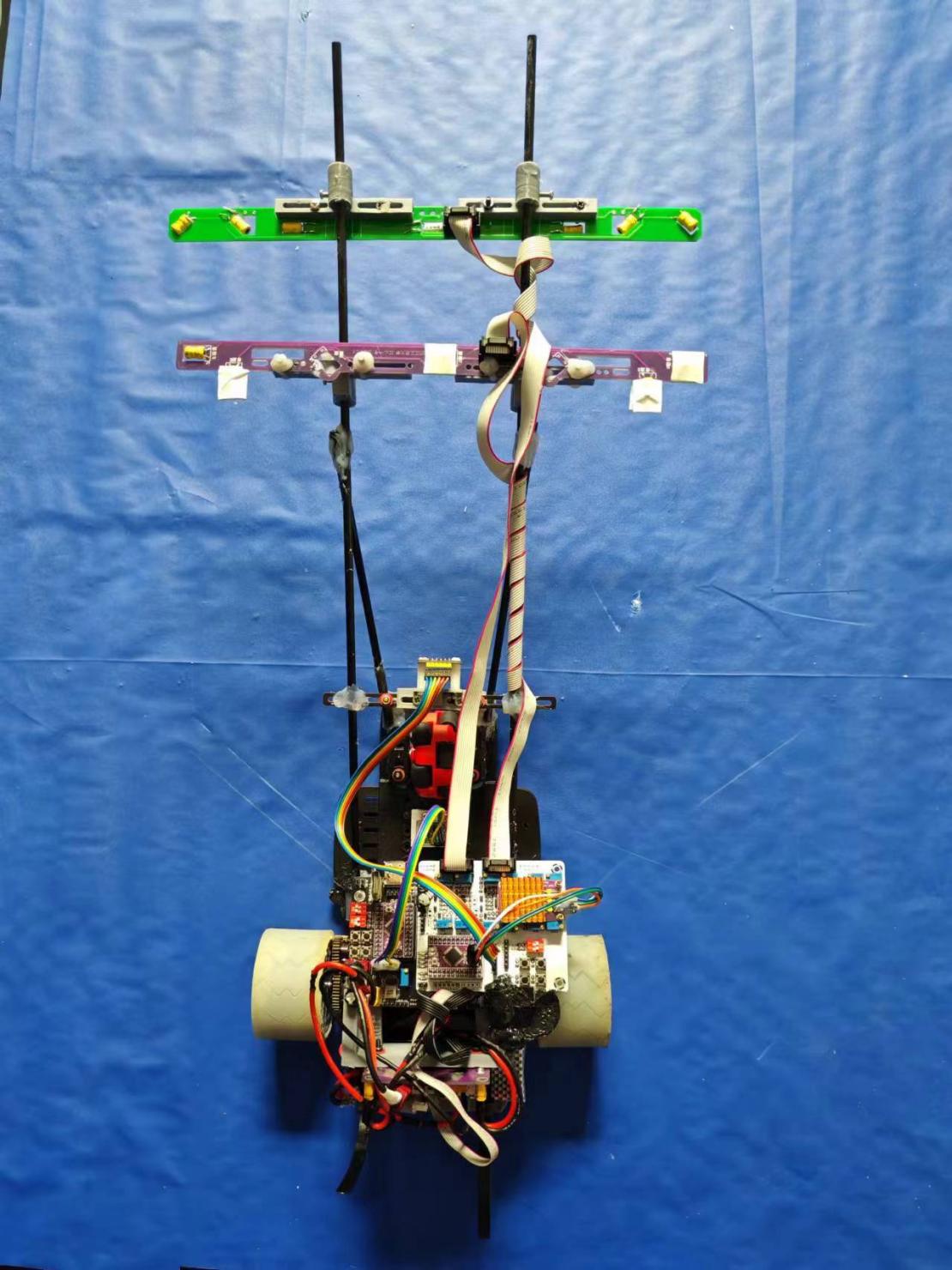
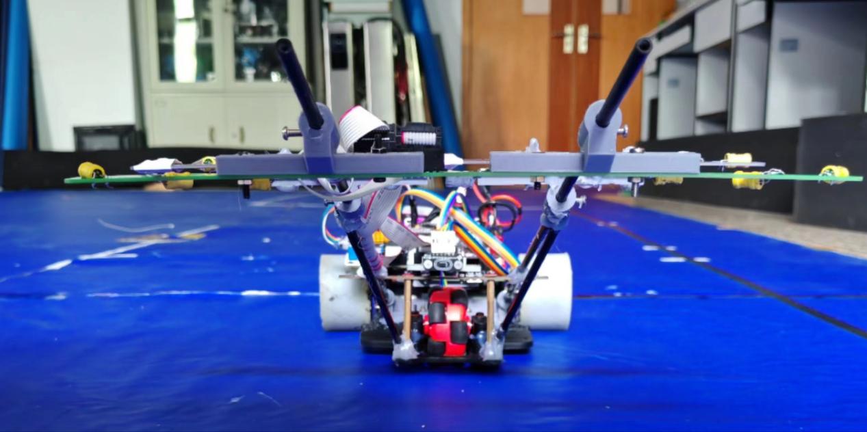
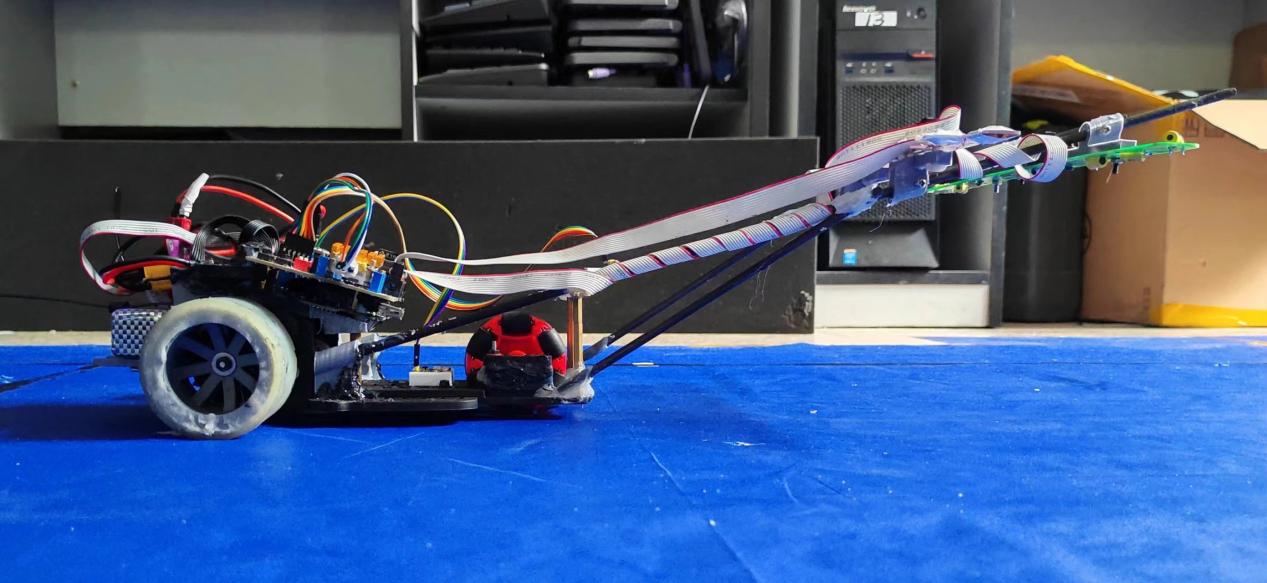
申报配置与源码版本Declared configuration & source revisions
版本对照:检查表是 2024 年“江心一号”的双 STC32F12K54 / 12 路 / 五板申报配置;仓库 README 的 STC32G12K128 是另一项描述。以下源码固定于 7261932,不能用 main 分支名称代替最终烧录版本。Revision map: the 2024 Jiangxin No. 1 inspection form declares dual STC32F12K54 controllers, 12 inductors and five boards. The repository README separately names STC32G12K128. Source analysis is pinned to 7261932; the main branch name does not identify the competition binary.
传感器与模拟前端Sensor & Analog Front-End
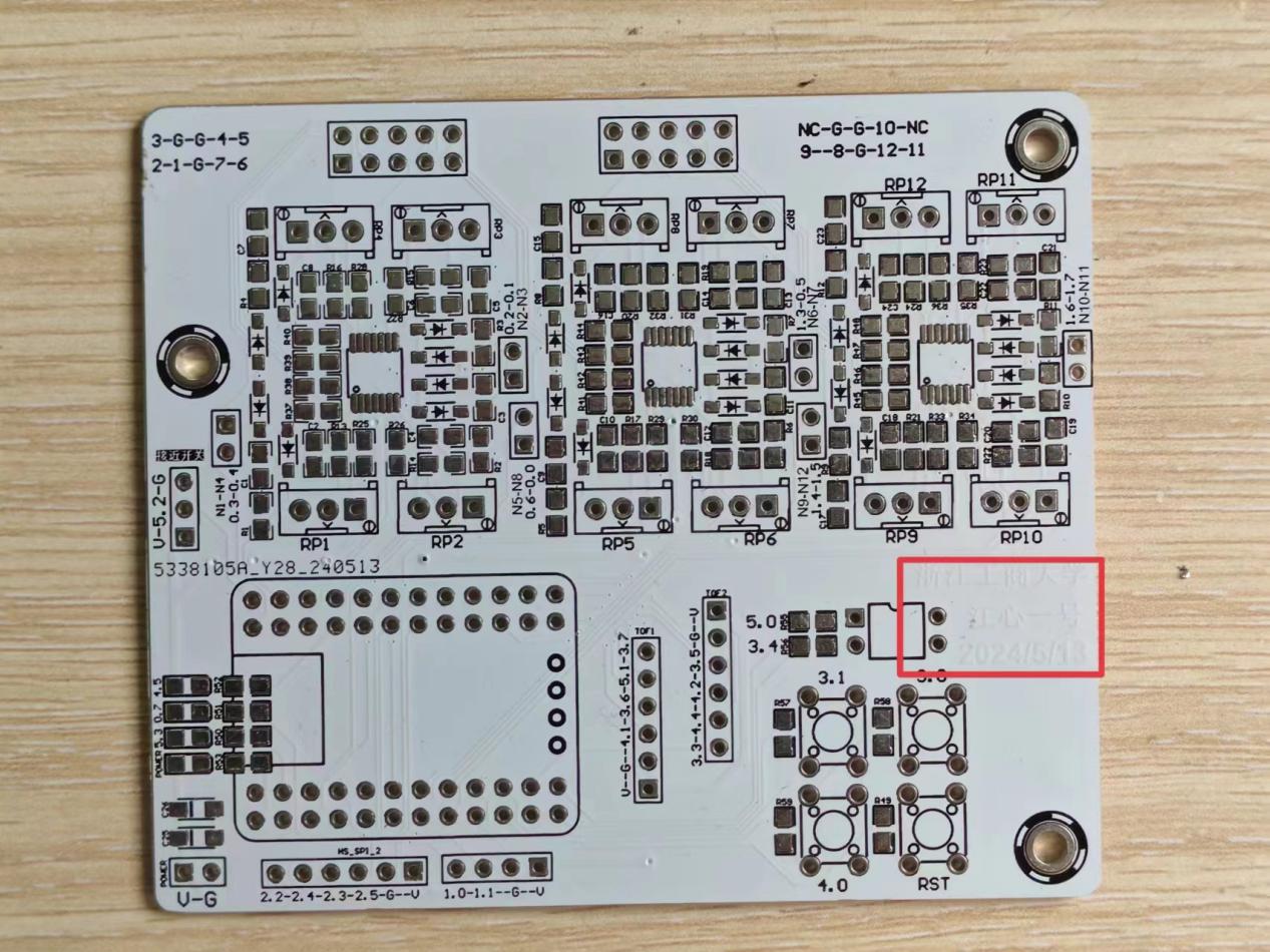
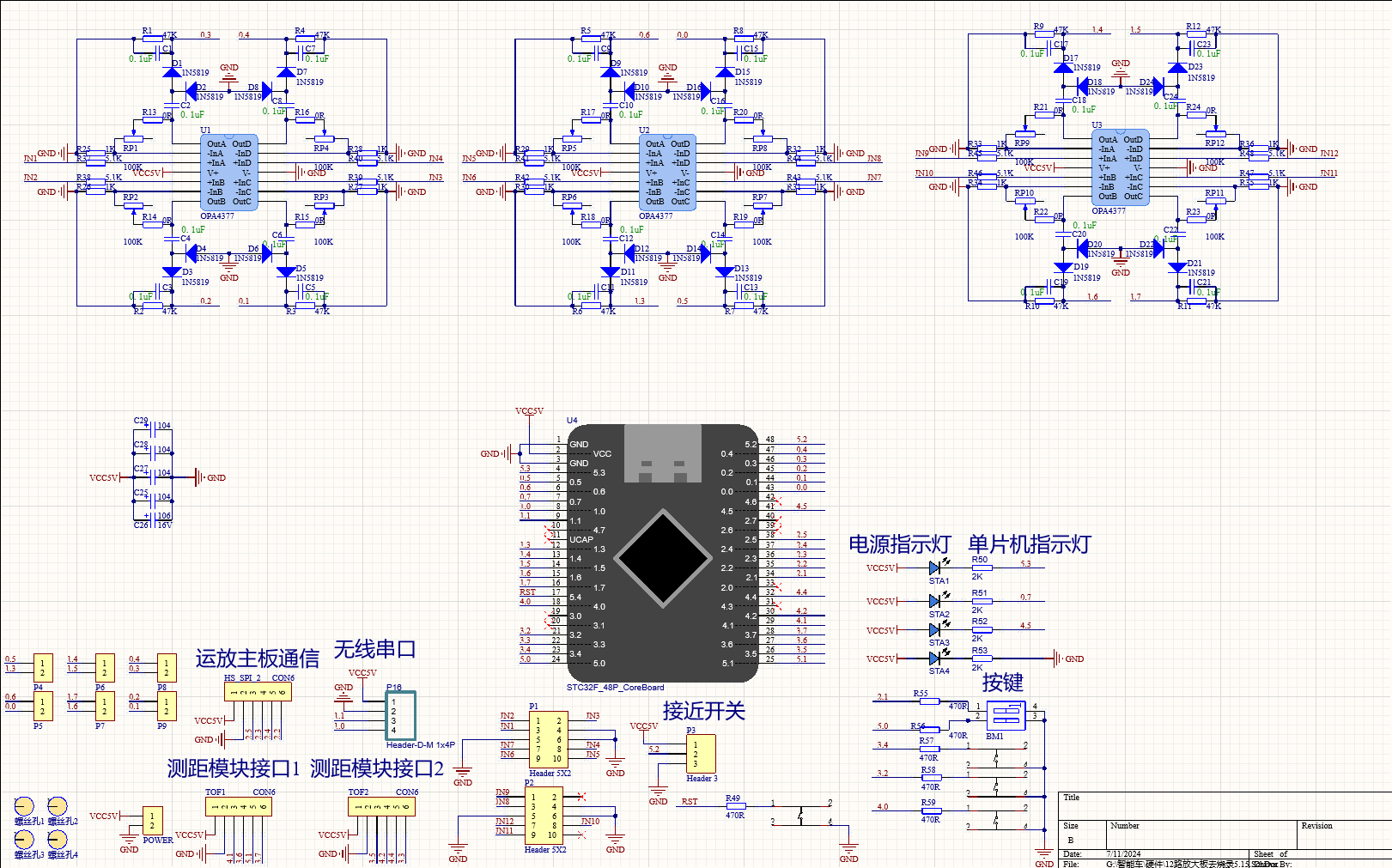
检查表图 10 标有 U1–U3 三颗 OPA4377、IN1–IN12、RP1–RP12 和第二块 STC32F 核心板。重复的四通道单元将电感信号接入调理网络,再送至 MCU;板上还绘有与运动主板通信的接口。Figure 10 labels three OPA4377 devices, IN1–IN12, RP1–RP12 and a second STC32F core board. Repeated four-channel cells connect inductive signals to conditioning networks and the MCU, alongside an interface to the motion controller.
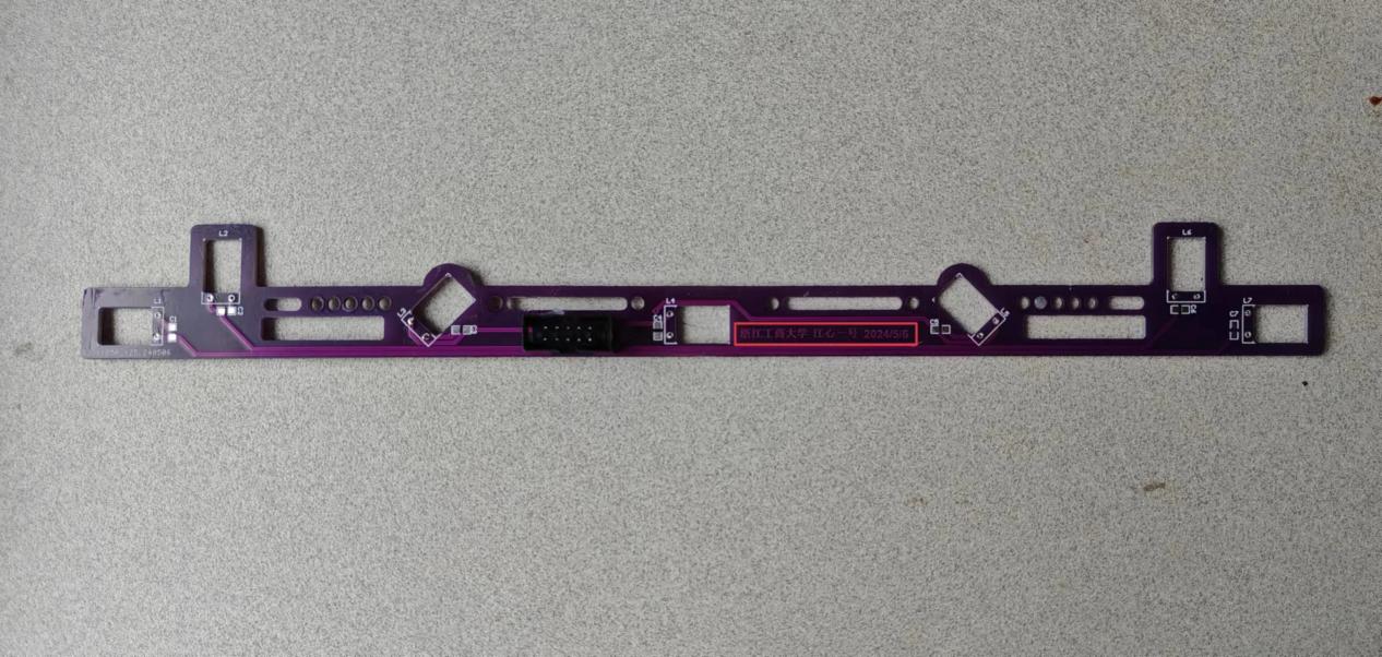
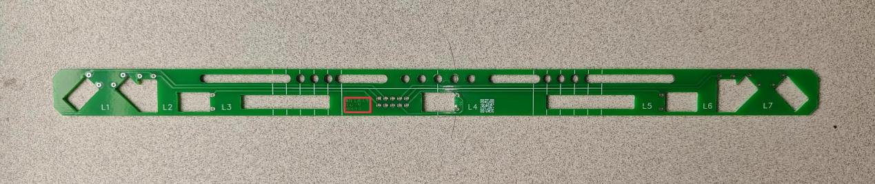
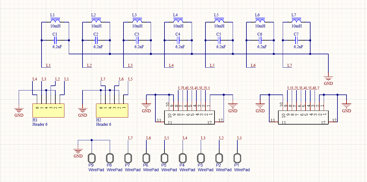
图 12 的单张电感杆图纸绘有 L1–L7 七个 LC 支路(标注 10 mH / 6.2 nF)。它不能单独解释整车 12 个电感的装配分配;两块杆的实际接线与通道映射仍需逐路核对。The single sensor-rod sheet in Figure 12 shows seven LC branches, L1–L7, labelled 10 mH / 6.2 nF. This does not establish how the vehicle’s 12 inductors were distributed; the two rods still require a channel-by-channel wiring map.
旧 ADC 实现仅处理 adc[1]–adc[10]。adc_aquire(count) 逐通道累加求均值,ADC_channel_quire() 以 10 次采样和每路 min/max 做归一化。均值可抑制波动,但增加采样时间;分母为零和通道饱和需要单独检查,不能把这段代码称为已完成的 12 路采样。The older ADC implementation processes only adc[1]–adc[10]. adc_aquire(count) averages repeated readings; ADC_channel_quire() requests ten samples and normalizes each channel using min/max values. Averaging trades noise reduction for acquisition time. Zero calibration span and saturation need separate checks; this is not a verified 12-channel implementation.
实现细节与工程取舍Implementation details & trade-offs
ADC_channel_quire() 按 (均值 − min) × 100 / (max − min) 归一化,旧代码将通道 1–5 与 6–10 分为两组 R1/R2/M/L2/L1。检查时应分别观察原始值、标定跨度和归一化值;该数组顺序不等于 2024 年两块电感杆的接线表。ADC_channel_quire() normalizes readings as (mean − min) × 100 / (max − min). The older code maps channels 1–5 and 6–10 into two R1/R2/M/L2/L1 groups. Inspect raw readings, calibration span and normalized values separately; this array order is not a wiring map for the 2024 sensor rods.
源码文件与函数 · 固定版本 7261932Source files & functions · revision 7261932
- USER/src/adc_aquire.c ↗
adc_aquire; ADC_channel_quire; ERR_process
PCB 与原理图设计PCB & Schematic Design
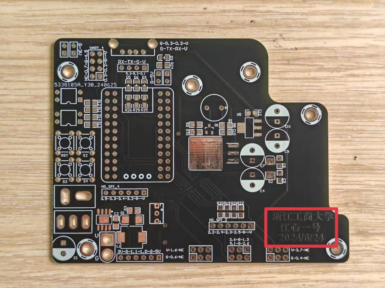
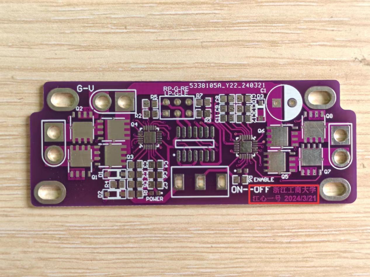
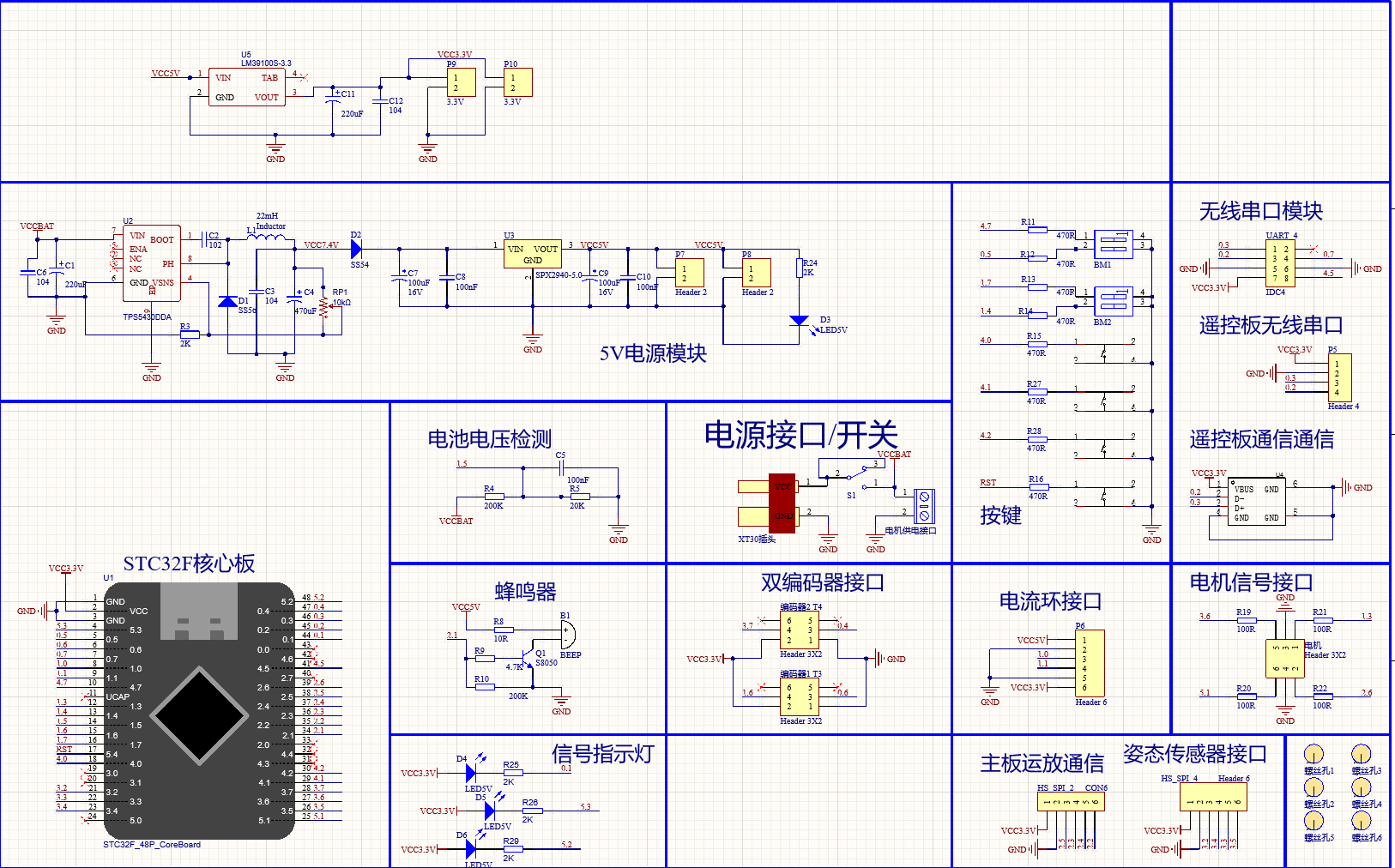
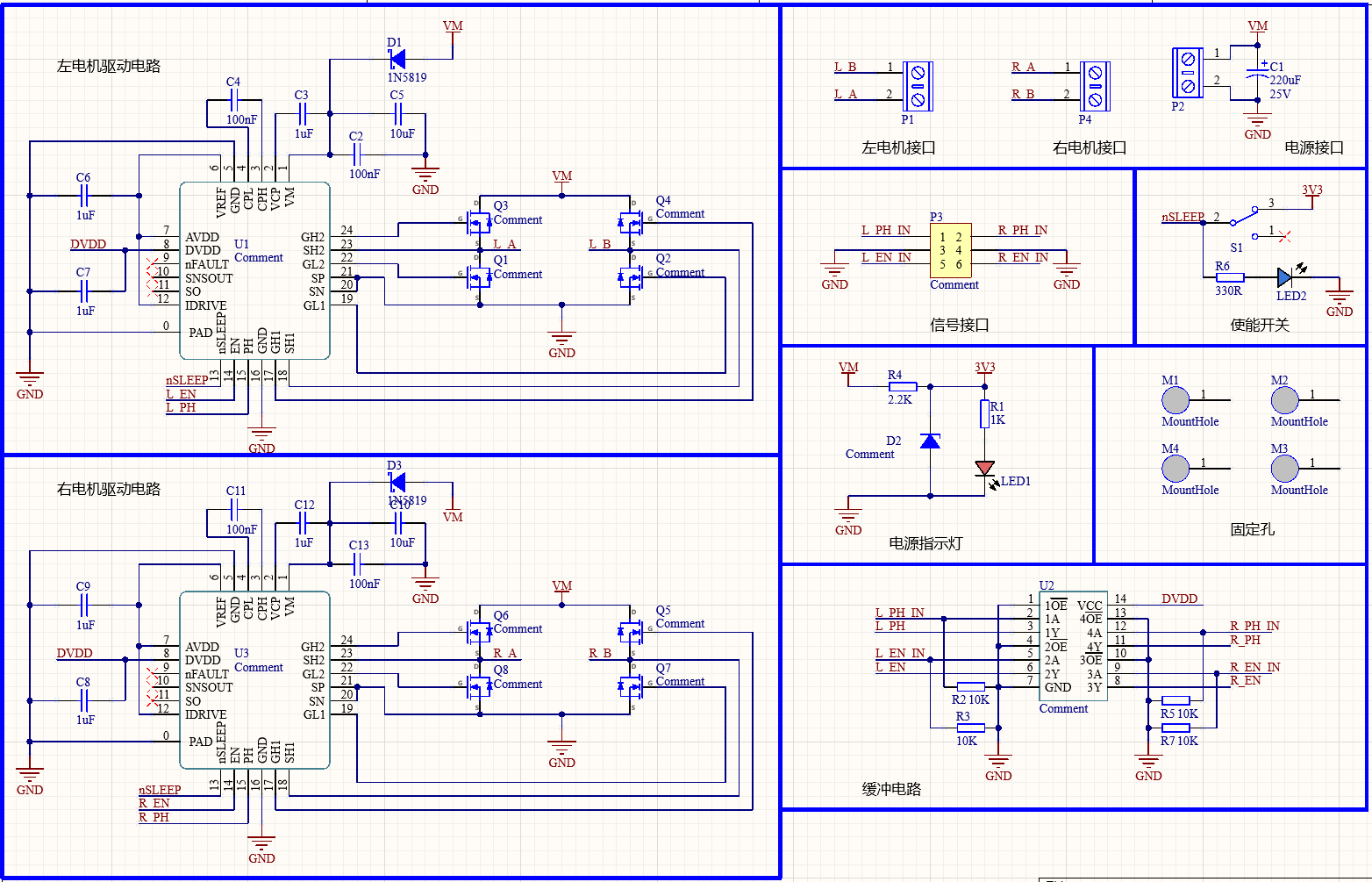
主板图 9 划分电源、电池电压检测、双编码器、电机信号、姿态传感器和主板—运放板通信接口。图 11 显示左右电机两组驱动电路、外置 MOSFET、PH/EN 控制信号与缓冲电路;部分器件型号栏为 Comment,因此不据此指定驱动芯片型号或额定功率。Figure 9 separates power, battery-voltage sensing, dual encoders, motor signals, attitude sensing and controller–amplifier communication. Figure 11 shows two motor-drive circuits with external MOSFETs, PH/EN signals and buffering. Some device values are “Comment”, so the sheet does not establish an exact driver part or rated power.
这些图纸支持讨论模块分工、模拟地参考、驱动回流及连接器信号方向。图纸上的无线接口仅表示设计接口,检查表申报“无无线通讯装置”。不同日期的 PCB 文件仍按独立设计修订记录。These sheets support discussion of module responsibilities, analog ground references, motor-current return paths and connector direction. Wireless headers are design interfaces; the inspection form declares no wireless communication device. PCB files with different dates remain separate design revisions.
高清设计归档High-resolution design archive
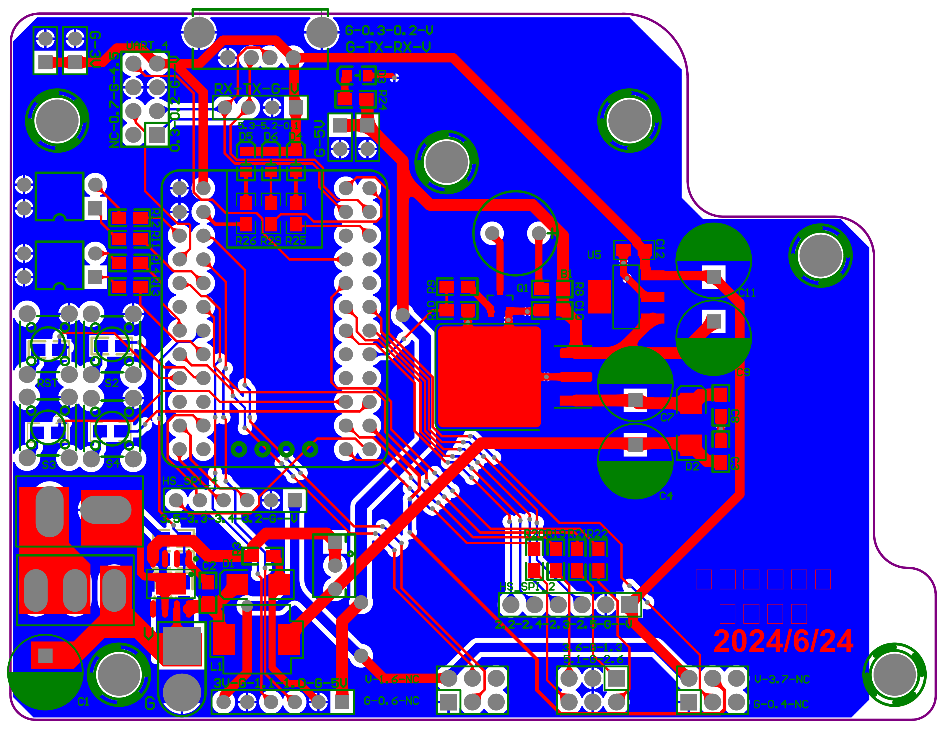
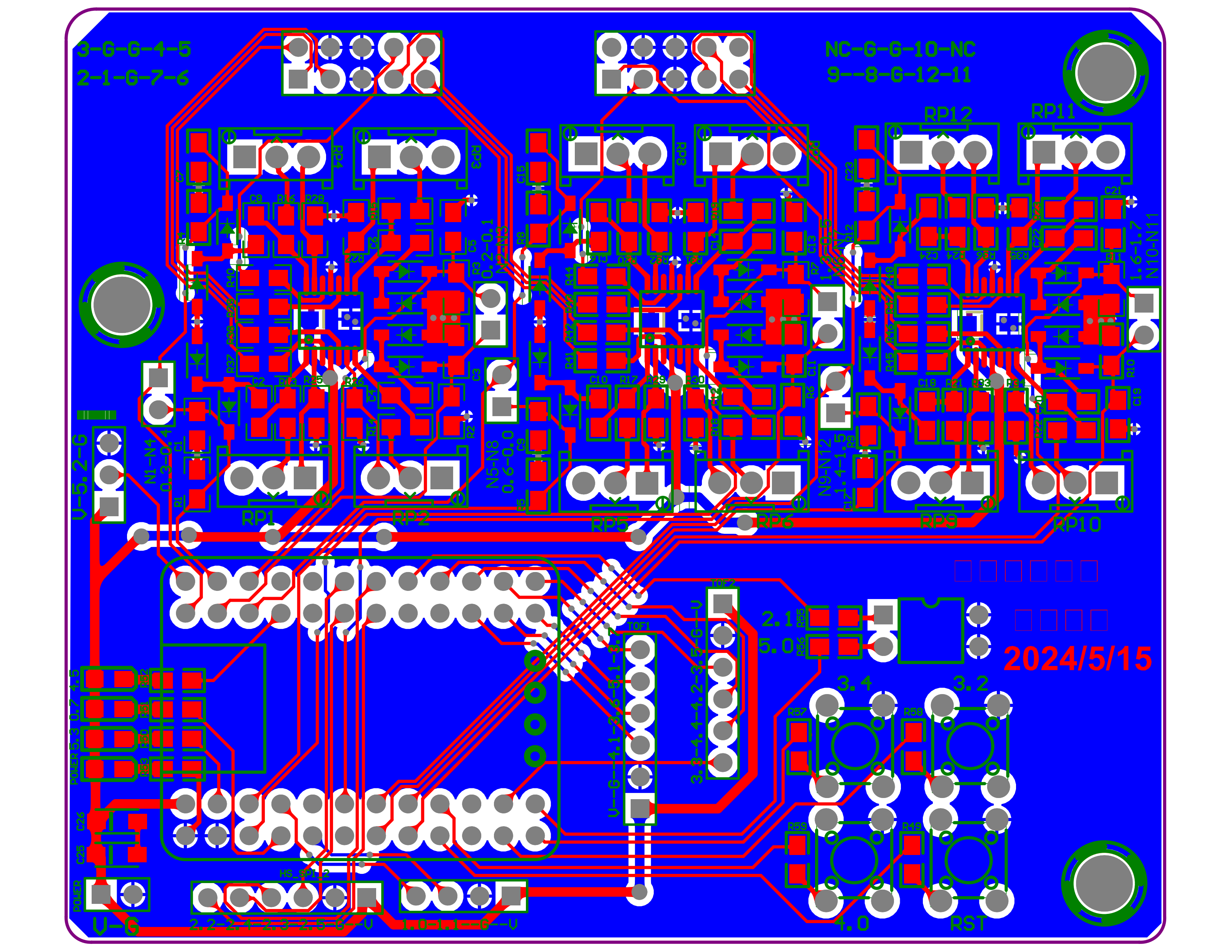
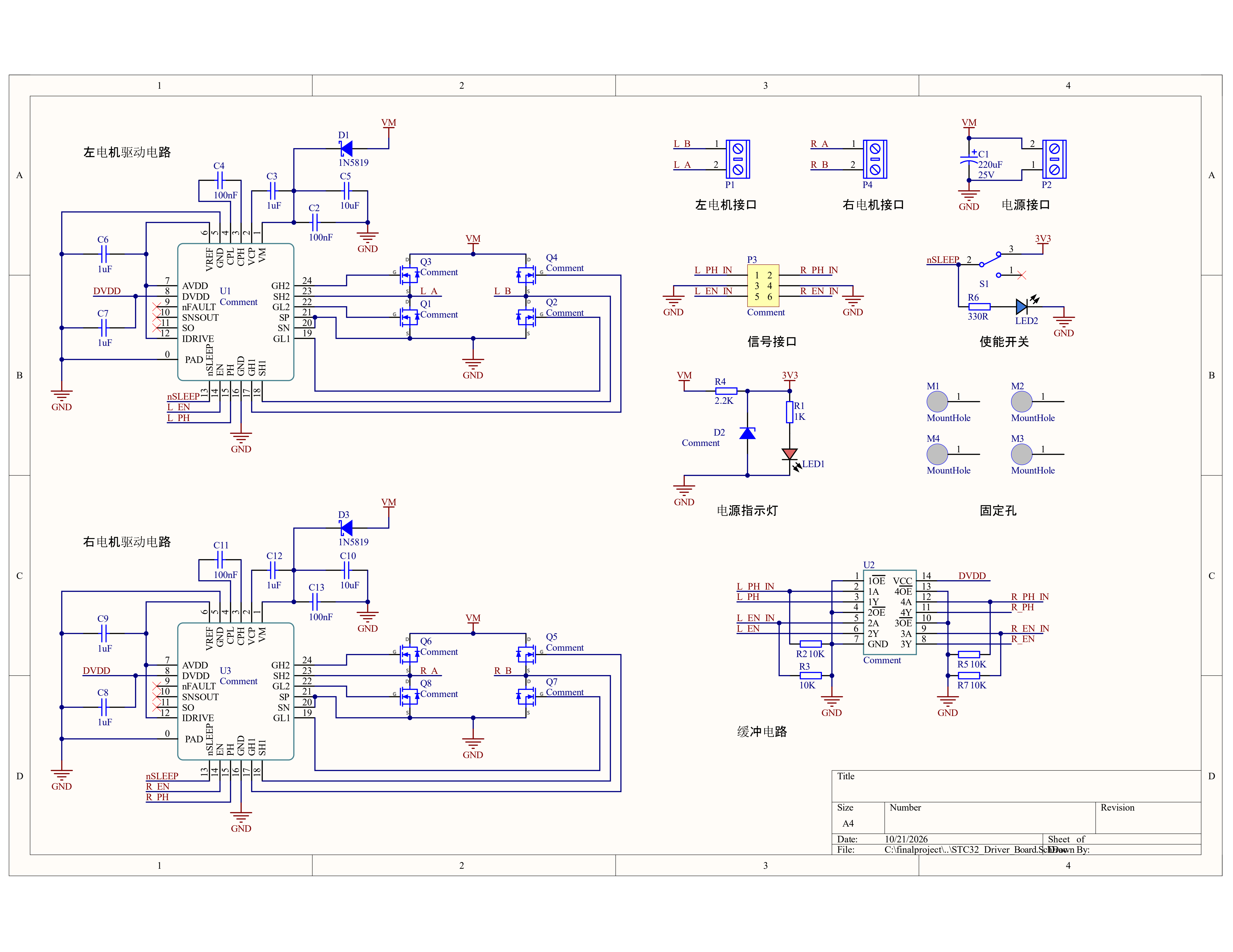
固件架构Firmware Architecture
顶层 USER/src/main.c 初始化 TIM_1 为 5 ms,并启用 SPI 从机。TM1_Isr() 依次读取 SPI_float、获取编码器计数、执行 motor_output()、处理 IMU,再调用 Element_Idef()。因此本次电机输出位于状态/目标更新之前,分析时要考虑前一周期的目标值。5 ms 是配置值,并非示波器实测周期。Top-level USER/src/main.c configures TIM_1 for 5 ms and enables an SPI slave. TM1_Isr() reads SPI_float, samples encoder counts, calls motor_output(), processes the IMU, then calls Element_Idef(). Motor output precedes state/target updates, so analysis must account for the previous cycle’s targets. The 5 ms value is configuration, not a measured period.
SPI_Isr() 按帧头、载荷和帧尾解析 float/uint/uchar;spi_slave_init() 使用 SPI_CH2,SCLK P2.5、MOSI P2.3、MISO P2.4。现有解析没有提供 CRC、序号或数据新鲜度超时,因此通信异常下的停止策略应作为后续验证点。SPI_Isr() parses float, uint and uchar frames using headers, payloads and trailers. spi_slave_init() uses SPI_CH2 on SCLK P2.5, MOSI P2.3 and MISO P2.4. The parser provides no CRC, sequence number or freshness timeout, making stale-data handling an explicit validation topic.
smart-elecar/USER 是另一目录实现,不是另一 Git 分支:main.c 配置 TIM_4 为 5 ms,TM4_Isr() 每次读取编码器并更新电机,每两个中断调用 MPU_Process()、ADC_channel_quire() 和 Element_Idef()。该目录直接采集 10 路 ADC,不能作为上面 SPI 从机的已匹配采集端。smart-elecar/USER is a separate source directory, not a separate Git branch. Its main.c configures TIM_4 for 5 ms; TM4_Isr() updates encoders and motors each interrupt, and calls MPU_Process(), ADC_channel_quire() and Element_Idef() every second interrupt. It directly samples ten ADC channels and is not established as the matched acquisition peer of the SPI slave.
实现细节与工程取舍Implementation details & trade-offs
SPI 浮点帧为 0x07 + 4 字节载荷 + 0x0A,接收端按低字节优先重组;uint 与 uchar 另用不同帧标记。静态复核发现 uchar 分支采用帧尾“不等于”条件,与其余分支相反。可用正确帧尾、错误帧尾及断流输入检查解析和失联处理;这是一项待台架验证的代码观察。The SPI float frame is 0x07 + four payload bytes + 0x0A, reconstructed least-significant byte first; uint and uchar use separate markers. Static review finds that the uchar branch uses a not-equal trailer condition, unlike the other branches. Valid-trailer, invalid-trailer and interrupted-stream inputs would test parsing and loss handling; this observation still needs bench validation.
源码文件与函数 · 固定版本 7261932Source files & functions · revision 7261932
- USER/src/main.c ↗
main - USER/src/isr.c ↗
TM1_Isr; SPI_Isr - USER/src/data.c ↗
spi_slave_init; spi_send_float - smart-elecar/USER/src/isr.c ↗
TM4_Isr
控制算法Control Algorithms
顶层 counte_quire() 读取并清零左右脉冲计数,结合方向引脚确定符号。mode_choose() 用基础速度、方向 PID 和 z_gyro 修正生成左右目标;motor_output() 计算速度误差、调用位置式 PID,再设置方向与 PWM 占空比。源码中的 6500 输出上限是计数限幅,不能直接换算为实际车速。Top-level counte_quire() reads and clears left/right pulse counts and resolves their sign using direction pins. mode_choose() combines base speed, steering PID and z_gyro correction into wheel targets. motor_output() computes speed error, applies position-form PID, then sets direction and PWM duty. Its 6500 output cap is a numeric limit, not a measured vehicle speed.
顶层 Element_Idef() 包含循迹启停与 SPI_float≥500 的停止条件;car_strategy() 的多个 case 为空,element.c 的 Hall_detection() 也为空。仅凭变量名不能宣称完整圆环、坡道或避障状态机已在此版本实现。Top-level Element_Idef() handles tracing/start-stop state and a SPI_float≥500 stop condition. Multiple car_strategy() cases and Hall_detection() in element.c are empty. Variable names alone do not establish complete roundabout, ramp or obstacle handling in this revision.
实现细节与工程取舍Implementation details & trade-offs
控制取舍:mode_choose() 对左右目标各调用一次同一 Forward_PID,函数每次都会更新积分与 last_err,因而两次计算不是无状态的同一修正量。PID_Loc_direction_Control() 另有 err > 4 && err < −4 的不可满足条件。速度环先算 PID 输出、再限制积分、最后把 PWM 数值限制到 6500;这些细节适合用单周期记录复核,而非直接推断赛道表现。Control trade-off: mode_choose() calls the same Forward_PID once for each wheel target. Each call updates the integral and last_err, so the two calls are not a stateless shared correction. PID_Loc_direction_Control() also contains an impossible err > 4 && err < −4 condition. The speed loop calculates PID output before limiting the integral, then caps the PWM value at 6500. These details warrant cycle-by-cycle review, not claims about track performance.
源码文件与函数 · 固定版本 7261932Source files & functions · revision 7261932
- USER/src/motor.c ↗
counte_quire; motor_output; PID_Loc_motor_Control; PID_Loc_Control; PID_Loc_direction_Control - USER/src/carcontrol.c ↗
mode_choose; Element_Idef; car_strategy - USER/src/element.c ↗
Hall_detection
调试与验证Debugging & Validation
建议验证顺序:供电与参考地 → 逐路模拟输出 → ADC 原始值/标定跨度 → SPI 帧与更新时间 → 左右目标速度 → 编码器符号 → PWM 与电机方向。分别记录输入、目标、反馈和输出,才能区分模拟饱和、通信过期和控制参数问题。A practical validation sequence is power/reference ground → per-channel analog output → ADC readings/calibration span → SPI frames/freshness → wheel targets → encoder signs → PWM/motor direction. Recording inputs, targets, feedback and output separately helps distinguish analog saturation, stale communication and tuning issues.
整车照片、板卡实物和电路图展示系统构成;代码解析展示采样、通信与控制逻辑。验证范围:文档与源码分析,不含本次硬件复测或新的性能测量。Vehicle photographs, board images and schematics document the system, while code analysis explains acquisition, communication and control. Validation scope: documentation and source analysis, without a new hardware test or performance measurement.
实现细节与工程取舍Implementation details & trade-offs
编码器链路:counte_quire() 先读取并清零计数,再由方向引脚确定正负。代码用 1.859375 乘脉冲数;该系数依赖轮径、传动比、编码器分辨率和调用周期,未经机械参数与时间基准复核,不将 Current_Speed 或累加的 distance 直接标成实测物理速度/距离。Encoder path: counte_quire() reads and clears counts, then resolves sign from direction pins. The code multiplies counts by 1.859375. That factor depends on wheel diameter, transmission ratio, encoder resolution and call interval; Current_Speed and accumulated distance are not presented as measured physical units without checking those assumptions.
源码文件与函数 · 固定版本 7261932Source files & functions · revision 7261932
- USER/src/motor.c ↗
counte_quire; motor_output
竞赛成果Competition Results
2024 年第十九届全国大学生智能汽车竞赛浙江赛区本科电磁组三等奖。该结果沿用已有竞赛资料;2023 年室外创意赛全国二等奖属于 ADV 项目,不与本项目合并。Third prize in the undergraduate electromagnetic category, Zhejiang regional competition of the 19th National University Students Smart Car Competition, 2024. This follows the existing competition record. The 2023 outdoor creative-design national second prize belongs to ADV.
我的实际工作My Contributions
在团队中参与硬件接口、嵌入式 C 开发、采样与控制调试及整车联调。底层驱动采用逐飞库;逐板 Layout 分工与最终烧录版本保留在工程备注中说明。Contributed to hardware interfaces, embedded C development, acquisition/control debugging and vehicle integration within the team. Low-level drivers use Seekfree libraries; per-board layout roles and the final flashed revision are addressed in Engineering Notes.
MECHANICAL DESIGN / PROTOTYPING
轮胎与模具设计:V1 → V2Tire & Mold Design: V1 → V2
我负责本项目轮胎结构与硅胶轮胎成型模具设计、胎面纹理制作及硅胶材料配制。以下照片和视频分别记录第一版与第二版轮胎原型的可见结构。I worked on tire structure and silicone tire mold design, tread texture fabrication, and silicone material preparation. The photo and video document the visible structures of two prototype iterations.
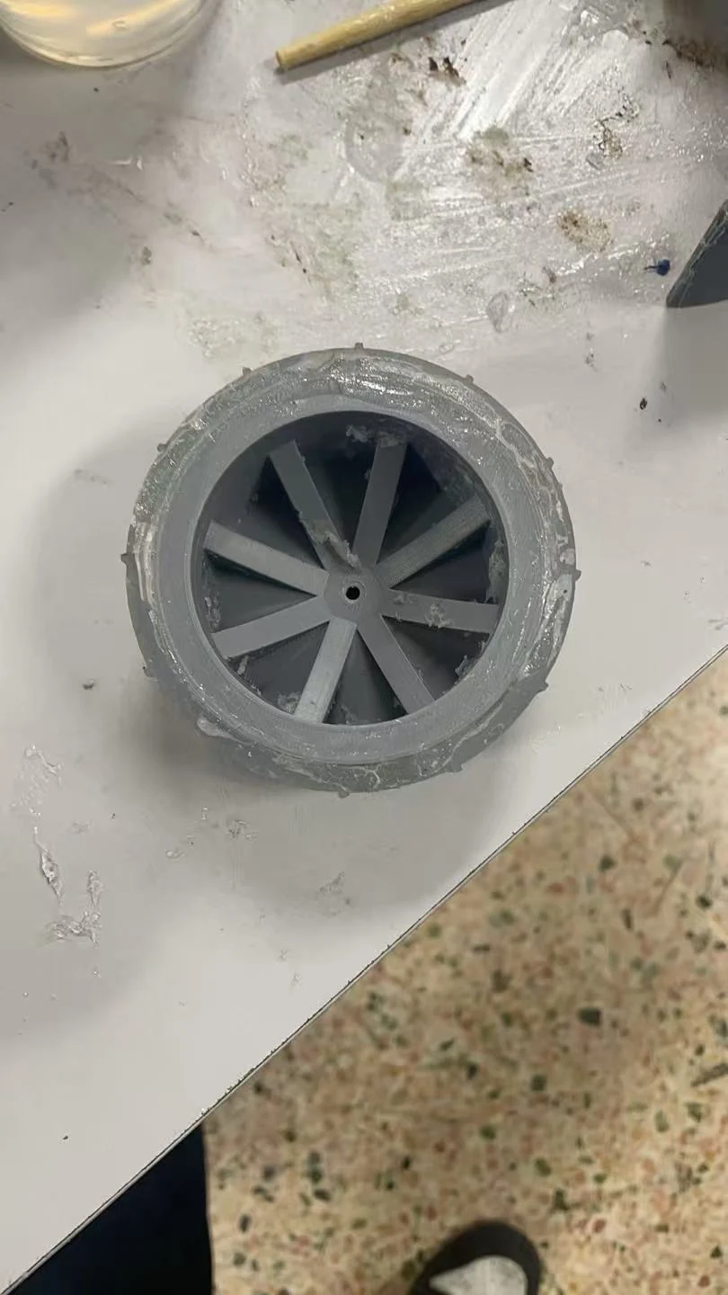
展示范围:两版原型的外观与结构迭代;影像不代表实车性能测试。Scope: prototype appearance and structural iteration; the media do not represent on-vehicle performance testing.
技术栈Tech Stack
工程技术深入Technical Deep Dive
把参赛车模申报、模拟电路资料与固件分支放在各自版本中阅读:从电感输入到控制输出逐层说明,同时保留 12 路硬件与旧 10 通道代码之间的明确边界。Read the competition declaration, analog design material and firmware branches in their own revision contexts, following sensing through control while keeping the 12-sensor hardware distinct from an older 10-channel code branch.
工程问题与模块职责Engineering question and responsibilities
怎样把多路电感信号变成可调试的路径误差和电机响应,同时避免混用硬件与代码版本?How can inductive channels become a debuggable path error and motor response without mixing hardware and firmware revisions?
2024 电磁组检查表提供车模和五板职责;原理图预览提供模拟通道结构;所读控制代码提供算法和调度的版本化分析,不被自动认定为最终参赛固件。The 2024 inspection form establishes the declared vehicle and five-board roles. Schematic previews show analog channels; reviewed code supports revision-specific algorithm and scheduling analysis without being designated final competition firmware.
硬件信号链与版本化固件阅读Hardware signal chain and revision-specific firmware
检查表 / 模拟结构Declared hardware / analog structure
- 0112 路电感 / 双电磁杆12 inductors / two rods
- 02OPA4377 调理OPA4377 conditioning
- 03ADC / MCU 控制接口ADC / MCU interfaces
- 04PWM / 驱动 / 车体PWM / driver / vehicle
归档 10 通道分支Archived 10-channel branch
- 01重复采样求均值Repeated acquisition / mean
- 02逐通道归一化Per-channel normalization
- 03误差 / 状态处理Error / state handling
- 04左右目标速度 / PWMWheel targets / PWM
01车模、五板职责与传感器Vehicle, five-board roles and sensors
团队申报配置Team Declaration
检查表是团队填写的申报/检查资料。它列出三轮车模、两个 STC32F12K54、12 个电感、一个 ToF mini plus 和一个 MPU6050;3S 电池的 11.1 V 为标称值,不是本轮测得电压。The inspection form is a team declaration and inspection record. It lists a three-wheel vehicle, two STC32F12K54 MCUs, twelve inductors, one ToF mini plus and one MPU6050. The 3S battery’s 11.1 V is nominal, not a voltage measured in this review.
| 对象Item | 内容与范围Description and scope |
|---|---|
| 主控与传感Controllers & sensing | 双 STC32F12K54;12 电感;ToF mini plus;MPU6050Two STC32F12K54; 12 inductors; ToF mini plus; MPU6050 |
| 五块板Five declared boards | 两块电磁杆、一块运放板、一块驱动板、一块主板Two inductor rods, one amplifier, one driver, one mainboard |
| 现成模块Purchased modules | STC32 核心板、MPU6050、ToF、OLED;不把额外归档电源板加入这份五板清单STC32 core boards, MPU6050, ToF and OLED; a separately archived power board is not added to this five-board list |
| 结构与供电Structure & supply | 三轮车模;申报约 580×215×180 mm;一块 3S、标称 11.1 V 电池Three-wheel vehicle; declared approx. 580×215×180 mm; one nominal 11.1 V 3S battery |
| 申报限制Declared configuration | 无转向舵机、无额外伺服、无无线通信或 GPS/RTKNo steering servo, extra servos, wireless communication or GPS/RTK |
来源:2024 车模技术检查表,配置与板卡表Source: 2024 vehicle inspection form, equipment and board tables
0212 路模拟前端与板级接口Twelve-channel analog front-end and interfaces
项目资料Project Records
归档放大板原理图预览标有 U1–U3 三颗 OPA4377、IN1–IN12 和 RP1–RP12;重复的四通道分组、VCC5V 网络和核心板接口可见。可据图说明通道调理与调节网络,但不能仅凭小图给出每路实测增益和带宽。The archived amplifier schematic preview labels three OPA4377 devices (U1–U3), IN1–IN12 and RP1–RP12. Repeated four-channel groups, VCC5V and core-board interfaces are visible. These support discussion of conditioning and adjustment networks, not measured per-channel gain or bandwidth.
工程检查可按电感输入、模拟输出、ADC 数值及执行响应分段,逐路核对地参考、幅度范围和标定一致性。图中的接口/无线串口位置不代表检查表对应车模实际启用了无线模块。An engineering review can follow inductive input, analog output, ADC readings and actuator response, checking ground reference, signal range and calibration consistency channel by channel. A connector or wireless-serial position in a drawing does not mean wireless hardware was enabled on the declared vehicle.
来源:归档放大板原理图预览;与检查表交叉核对Source: archived amplifier schematic preview, cross-checked against the form
03采样、调度与控制代码Acquisition, scheduling and control code
归档代码Archived Code
所读 adc_aquire 分支对 adc[1]–adc[10] 的十个通道重复采样、累加并除以 count;ADC_channel_quire 调用 adc_aquire(10),再按每路最小/最大值做归一化。这里的“10”同时出现在通道数和均值样本数中,二者不能与申报的 12 个电感混淆。The reviewed adc_aquire branch repeatedly samples ten channels, adc[1]–adc[10], sums them and divides by count. ADC_channel_quire calls adc_aquire(10), then normalizes using each channel’s minimum and maximum. Ten appears both as a channel count and an averaging count; neither should be substituted for the twelve declared inductors.
另一控制路径的定时中断读取 SPI_float 误差信息、编码器计数,随后调用 PWM 输出、IMU 处理和状态识别;直行模式以基础速度加减方向修正和陀螺项形成左右目标速度。主循环还含无线调试初始化,因此不把该分支直接称为“无无线参赛车”的最终配置。Another control path’s timer ISR reads SPI_float error information and encoder counts, then invokes PWM output, IMU processing and state handling. Straight-running mode combines base speed with steering and gyro terms to form wheel targets. Its main loop also contains wireless-debug initialization, so this branch is not identified as the final no-wireless competition configuration.
来源:归档 ADC、状态控制、定时中断代码;版本分别记录Source: archived ADC, state-control and timer-ISR code, retained by revision
04标定、滤波与控制时序的取舍Calibration, filtering and control timing
工程分析Engineering Analysis
采样求均值可以降低随机波动,但会增加取样工作量;归一化依赖有效且非零的标定跨度。分析时应同时检查每路 ADC 范围、归一化分母与控制输入的更新顺序,而非只改 PID 增益。Averaging can reduce random variation at the cost of acquisition work. Normalization requires a valid, nonzero calibration span. Review should check ADC range, the normalization denominator and control-input update order, rather than changing PID gains alone.
源码的定时调用参数与部分注释并不完全一致,因此不在页面给出“最终控制频率”或比赛实测 PID 参数。采集、误差传输和 PWM 更新应绑定同一套固件与板卡版本后再定量解释。Timer-call parameters and some comments are inconsistent, so no final control frequency or competition-tested PID gains are claimed here. Acquisition, error transfer and PWM update should be tied to one firmware and board revision before quantitative interpretation.
工程分析:采样与调度实现的版本检查Engineering analysis: acquisition and scheduling revision checks
05从模拟通道到左右轮响应From analog channels to wheel response
工程分析Engineering Analysis
可执行的排查顺序是:供电与地→通道原始值→标定/归一化→SPI 传递误差→左右目标速度→编码器符号→PWM 方向。每个观察点对应不同问题层次,不能把接线或方向错误都归为控制参数问题。A diagnostic sequence is supply/ground, raw channels, calibration/normalization, SPI error transfer, wheel targets, encoder sign and PWM direction. Each observation belongs to a different fault layer; wiring and direction issues should not all be treated as control-tuning problems.
整车、板卡及原理图按检查表原图和独立 EDA 修订分组呈现,用于说明系统结构与电路设计。动态性能应结合对应波形和道路测试记录讨论。Vehicle, board and schematic figures are grouped into inspection-form originals and separate EDA revisions to explain system and circuit design. Dynamic performance should be discussed alongside matching waveforms and track-test records.
工程分析:按信号链建立检查点Engineering analysis: checkpoints along the signal chain
06竞赛结果与个人工作范围Competition outcome and contribution scope
项目资料Project Records
结果仍准确对应 2024 第十九届全国大学生智能汽车竞赛浙江赛区本科电磁组三等奖。2023 室外创意设计赛的全国与南部赛区奖项列在 ADV,不并入本项目。The outcome remains third prize in the undergraduate electromagnetic category at the 2024 Zhejiang regional competition. National and Southern regional awards from the 2023 outdoor Creative Design entry are listed under ADV, not this project.
本人参与硬件、嵌入式开发与系统联调的既有范围保留;五块板的个人 Layout 分工及最终装车修订不由这份检查表或某个代码分支推定。My established involvement in hardware, embedded development and system integration is retained. Individual layout responsibility and final vehicle-board revisions are not inferred from this form or a code branch.
来源:竞赛记录、技术检查资料与项目分工Source: existing competition records, inspection material and reviewed contribution scope
面试深入讨论Interview Deep Dive
从设计问题与已有实现出发,进一步讨论边界、观察量和验证方法。Follow the design questions and implementation details into scope, observables and validation methods.
12 个电感与十通道 ADC 代码如何对应?How do twelve inductors relate to ten-channel ADC code?
目前不能直接对应:前者来自申报检查表,后者来自特定归档分支。需用完整固件、主从分工和接线表建立版本映射。They are not directly mapped: one comes from the inspection declaration and the other from a specific archived branch. Full firmware, controller roles and wiring records are needed.
为何先检查归一化,再讨论 PID?Why inspect normalization before PID tuning?
逐通道最小/最大值决定输入尺度;量程、分母或方向错会改变控制误差,PID 调参不能替代前端校验。Per-channel minima/maxima determine input scale. Range, denominator or direction errors alter control error; PID tuning does not replace front-end checks.
双 MCU 的实时性应怎样说明?How should dual-MCU timing be explained?
先说明误差数据产生、通信、消费和PWM更新的顺序,再依据同一固件的定时器配置与测量记录讨论周期;函数名和注释本身不足。Explain production, transfer and consumption of error data and PWM updates first, then discuss timing from matching configuration and measurements. Names and comments alone are insufficient.
工程备注 · 阶段与版本Engineering Notes · stage & revisions
- 12 路双 STC32F 系统与旧 10 路 STC32G 固件分别记录;各 PCB 修订的装车对应及逐板个人 Layout 范围另行确认。The 12-channel dual-STC32F system is distinct from older 10-channel STC32G firmware. Vehicle-to-PCB revision mapping and personal layout responsibility are board-specific.
- 本页奖项仅对应 2024 浙江赛区电磁组;2023 年国家二等奖属于另一段竞赛经历。The award here belongs to the 2024 Zhejiang electromagnetic entry. The 2023 national second prize is a separate competition experience.
硬件架构与 PCB 设计Hardware Architecture & PCB Design
从电源、传感接口和控制器到板级布局,补充介绍项目的硬件设计资料。Power, sensor interfaces, controller design and board layout provide a closer look at the project hardware.
STC32 模拟前端与控制板STC32 Analog Front-End & Control Boards
Competition Hardware · 设计资料Competition Hardware · design material
控制板、12 路放大板和供电模块构成板级设计资料。模拟前端采用重复通道布局,系统工作连接 OPA4377、ADC 与 MCU 控制。The design material includes a controller, a 12-channel amplifier and power modules. Repeated analog-channel layouts connect OPA4377 conditioning, ADC acquisition and MCU control.
设计背景与板卡定位Design Objective
将电感采样、模拟调理、控制和供电按板级接口划分,支持整车采样到执行的联调。Separate inductive acquisition, analog conditioning, control and power by board interfaces to support vehicle integration.
电路架构与主要器件Circuit Architecture
- 放大板图纸标注三颗 OPA4377 与 RP1–RP12 调节网络。The amplifier schematic material labels three OPA4377 devices and RP1–RP12 adjustment networks.
- 控制板可定位核心板插座、UART/HS_SPI、按键与电源区域。The controller layout identifies core-board headers, UART/HS_SPI, buttons and power sections.
- 供电、模拟和控制接口分别检查,结合 ADC 读数与 PWM 响应联调。Power, analog and control interfaces are checked separately alongside ADC readings and PWM response.
Layout 与电路讲解Layout & Circuit Walkthrough
- 设计资料支持讨论模拟通道重复布局、接口扇出、供电分区与底层铺铜。The design material supports discussion of repeated analog channels, interface fan-out, power placement and bottom-layer copper.
- 2024 浙江赛区本科电磁组三等奖对应系统项目经历。The 2024 Zhejiang undergraduate electromagnetic third prize belongs to the system project.
工程备注 · 完成阶段与分工Engineering Notes · stage & contribution
系统竞赛经历与板卡设计归档分层展示;各修订的制造、测试和装车对应按板卡记录。The competition system and board-design archive are presented separately; fabrication, tests and vehicle mapping are revision-specific.
项目工作包括硬件与嵌入式开发及系统联调;每块归档 PCB 的具体设计范围另按板卡说明。Project work includes hardware, embedded development and system integration; responsibility for each archived PCB is described separately.
- 12 路双 STC32F 与旧 10 路 STC32G 资料分别归档;逐板设计贡献及最终装车修订需具体确认。The 12-channel dual-STC32F and older 10-channel STC32G material are separate; personal board-design scope and final vehicle revisions require specific confirmation.